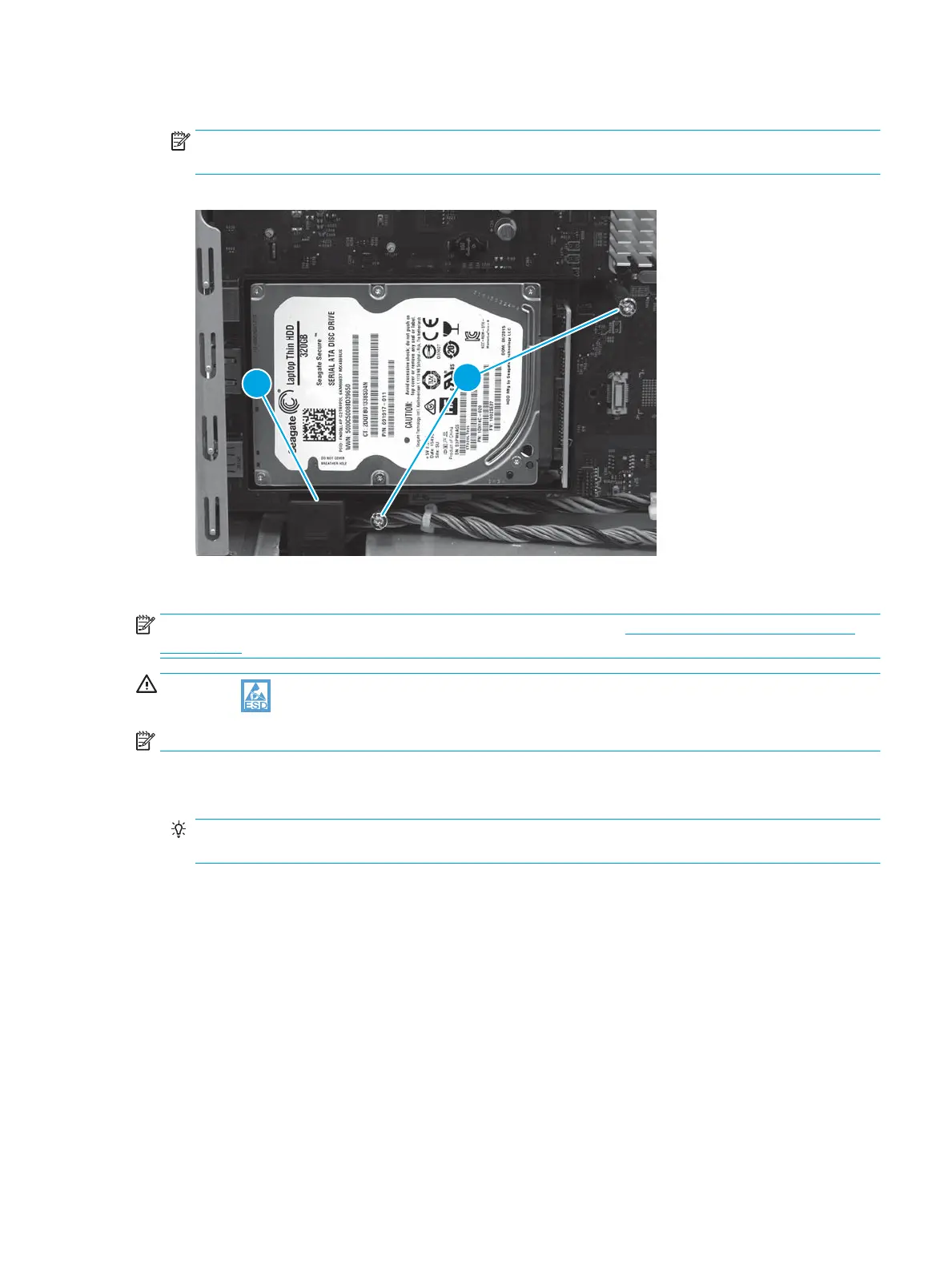
3. Install two thumbscrews (callout 1).
NOTE: If the connector (callout 2) was disconnected to make it easier to install the lower thumbscrew,
connect it now.
Figure 1-600 Install two thumb screws
Step 12: Install the fax PCA
NOTE: Fax models only. For all other models, skip this step and go to Step 13: Install the formatter cover
on page 370.
CAUTION: ESD-sensitive part.
NOTE: 586f/z printers only (optional for the 586dn).
1. Position the port (callout 1) on the fax PCA into the opening (callout 2) in the formatter case. Position
the edge of the fax PCA (callout 3) into the sheet-metal slot (callout 4) on the formatter case.
TIP: If a fax accessory is being installed on the 586dn printer, peel away the protective covering on the
outside of the formatter case to expose the fax port slot in the sheet metal frame.
ENWW Removal and replacement procedures 369
 Loading...