4. Starting at the right upper corner of the cover and working toward the left, push in along the top edge of
the cover to engage the bosses along the top of the cover.
Figure 1-955 Release the top edge of the cover
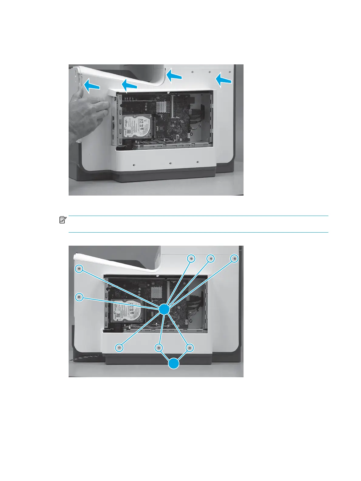
5. Install eight screws (callout 1).
NOTE: Two of these screws (callout 2) are a dierent type (machine screws) than the others. Make sure
that they are installed in the correct position.
Figure 1-956 Install eight screws
Step 20: Install the right cover (outer) (PM)
1. Position the bottom edge of the cover on the printer.
570 Chapter 1 Removal and replacement ENWW
 Loading...