4. Pass the cables and wire harness through the opening in the formatter cage, and then connect ve
connectors (callout 1).
TIP: The cable retainer (callout 2) is easily dislodged. Do not lose the retainer.
Figure 1-841 Disconnect connectors
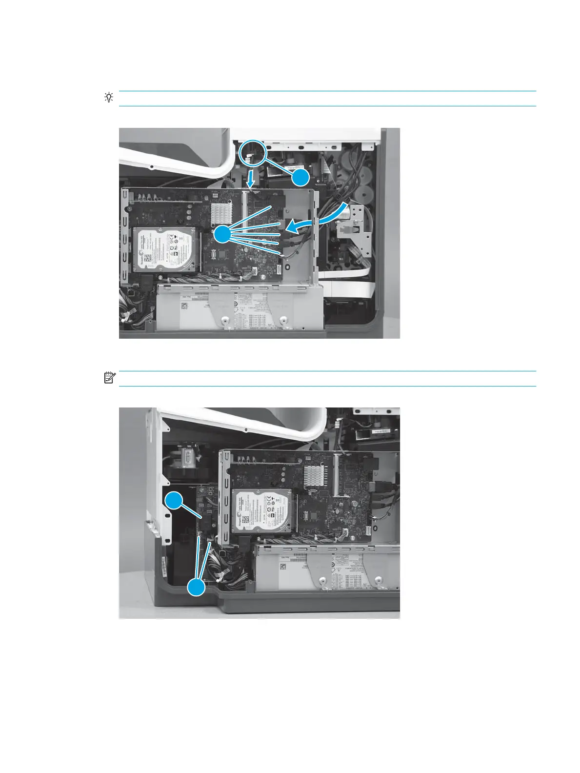
5. Connect one HMDI cable (callout 1), and then connect two connectors (callout 2).
NOTE:
Figure 1-842 Connect connectors
Step 19: Install the rear cover (PM)
1. Before proceeding, take note of the tabs and bosses on the rear cover.
ENWW Removal and replacement procedures 507
 Loading...