13. USING STO FUNCTION
13 - 6
13.2.2 Signal (device) explanations
(1) I/O device
Common terminal for input signal of STO1 and STO2
Inputs STO state 1.
STO state (base shut-off): Open between STO1 and STOCOM.
STO release state (in driving): Close between STO1 and STOCOM.
Be sure to turn off STO1 after the servo motor stops by the servo-off state or with
forced stop deceleration by turning off EM2 (Forced stop 2).
Inputs STO state 2.
STO state (base shut-off): Open between STO2 and STOCOM.
STO release state (in driving): Close between STO2 and STOCOM.
Be sure to turn off STO2 after the servo motor stops by the servo-off state or with
forced stop deceleration by turning off EM2 (Forced stop 2).
Common terminal for monitor output signal in STO state
Monitor output signal in STO1 state
STO state (base shut-off): Between TOFB1 and TOFCOM is closed.
STO release state (in driving): Between TOFB1 and TOFCOM is opened.
Monitor output signal in STO2 state
STO state (base shut-off): Between TOFB2 and TOFCOM is closed.
STO release state (in driving): Between TOFB2 and TOFCOM is opened.
(2) Signals and STO state
The following table shows the TOFB and STO states when the power is on in normal state and
STO1 and STO2 are on (closed) or off (opened).
Between TOFB1 and TOFCOM
(Monitoring STO1 state)
Between TOFB2 and TOFCOM
(Monitoring STO2 state)
Between TOFB1 and TOFB2
(Monitoring STO state of driver)
On: STO state (base circuit shut-off)
On: STO state (base circuit shut-off)
On: STO state (base circuit shut-off)
On: STO state (base circuit shut-off)
Off: STO state (base circuit shut-off)
On: STO state (base circuit shut-off)
Off: STO state (base circuit shut-off)
(3) Test pulse of STO input signal
Set the test pulse off time inputted from outside to 1 ms or less.
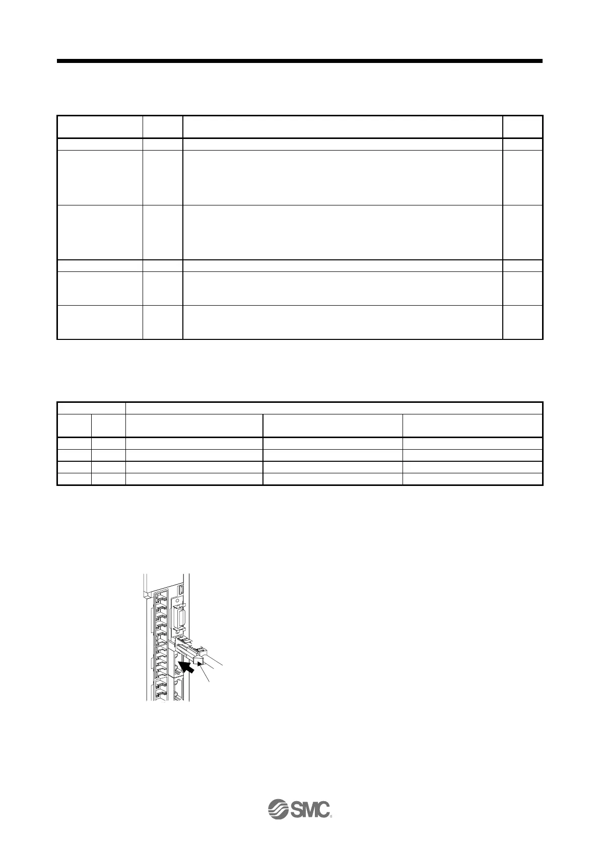
13.2.3 How to pull out the STO cable
The following shows how to pull out the STO cable from the CN8 connector of the driver.
While pressing knob 1) of the STO cable plug in the
direction of the arrow, pull out the plug 2).

 Loading...


