EasyManua.ls Logo

SMC Networks LECSN-T Series - App. 4.5 Signal; App. 4.5.1 Signal; App. 4.5.2 I;O device

SMC Networks LECSN-T Series
1046 pages
To Next Page IconTo Next Page
To Previous Page IconTo Previous Page
Loading...
APPENDIX
App. - 11
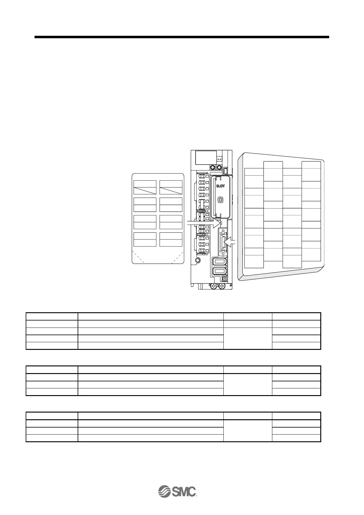
The connectors described by rectangles are safely separated from the main circuits described by circles.
The connected motors will be limited as follows.
(1) Servo motor series LE-
-
(2) Using a servo motor complied with IEC 60034-1 and Mitsubishi Electric encoder (OBA, OSA)
App. 4.5 Signal
App. 4.5.1 Signal
The following shows LECSN2-T5 signals as a typical example. For other drivers, refer to each driver
instruction manual.
CN3
1
2
3
5
4
6
7
9
8
10
11
12
13
14
15
16
17
18
19
20
LSP
MO1
TPR1
TPR2
DOCOM
DICOM
LZ
LSN
MO2
EM2
LG
MBR
LBR
LA
LB
LZR
LAR
ALM
DOG
INP
TOFB2
STO2TOFB1
STO1 STOCOM
2
CN8
1
4 3
6 5
8 7
TOFCOM
STO I/O signal
connector
App. 4.5.2 I/O device
Input device
Symbol
Device
Connector
Pin No.
EM2
Forced stop 2
CN3
20
STOCOM
Common terminal for input signals STO1/STO2
3
STO1
STO1 state input
CN8
4
STO2
STO2 state input
5
Output device
Symbol
Device
Connector
Pin No.
TOFCOM
Common terminal for monitor output signal in STO state
8
TOFB1
Monitor output signal in STO1 state
CN8
6
TOFB2
Monitor output signal in STO2 state
7
Power supply
Symbol
Device
Connector
Pin No.
DICOM
Digital I/F power supply input
5, 10
DOCOM
Digital I/F common
CN3
3
SD
Shield
Plate

Table of Contents

Related product manuals