3. SIGNALS AND WIRING
3 - 7
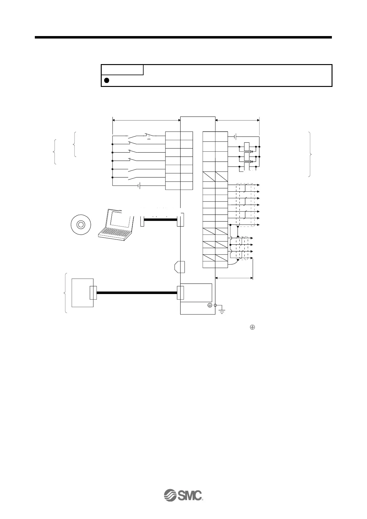
3.2 I/O signal connection example
EM2 has the same function as EM1 in the torque mode.
3.2.1 For sink I/O interface
20EM2
2
19
12
LSP
DOG
LSN
(Note 12)
CN3
(Note 12)
(Note 13)
CN3
13 MBR
9 INP
15 ALM
6 LA
16 LAR
7 LB
17 LBR
8 LZ
18 LZR
11 LG
RA1
RA2
RA3
DOCOM
TPR2
3
1
10TPR1
CN5
+
MO1
MO2
4
14
SD
Controller
(Note 1)
(Note 10)
24 V DC
(Note 2)
(Note 7)
SLOT
CN8
DICOM
5
(Note 4)
Forward rotation
stroke end
Reverse rotation
stroke end
Proximity dog
(Note 3)
Forced stop 2
(Note 6)
Touch probe 1
Touch probe 2
Servo amplifier
(Note 5)
MR Configurator2
USB cable
MR-J3USBCBL3M
(option)
(Note 8)
Main circuit
pow er supply
(Note 10) 24 V DC
10 m or less 10 m or less
Personal
computer
Encoder A-phase pulse
(differential line driver)
Encoder B-phase pulse
(differential line driver)
Encoder Z-phase pulse
(differential line driver)
(Note 14)
Electromagnetic brake
interlock
Malfunction (Note 11)
In-position
Control common
Analog monitor 1
± 10 V DC
Analog monitor 2
± 10 V DC
2 m or less
Plate
Network
module
(Note 9)
Short-circuit connector
(Packed with the servo
amplifier)
To prevent an electric shock, always connect the protective earth (PE) terminal (marked ) of the driver to the protective
earth (PE) of the cabinet.
Connect the diode in the correct direction. If it is connected reversely, the driver will malfunction and will not output signals,
disabling EM2 (Forced stop 2) and other protective circuits.
If the upper side does not have forced stop function, always install the forced stop 2 switch (normally closed contact).
When starting operation, always turn on EM2 (Forced stop 2), LSP (Forward rotation stroke end) and LSN (Reverse rotation
stroke end). (Normally closed contact)
You can change devices of these pins with [Pr. PD03], [Pr. PD05], and [Pr. PD06].
For the network connections, refer to chapter 18,19,20.
Configure a circuit to turn off EM2 when the main circuit power is turned off to prevent an unexpected restart of the driver.
When not using the STO function, attach the short-circuit connector came with a driver.
Supply 24 V DC ± 10% for interfaces from outside. Set the total current capacity to 300 mA. 300 mA is the value applicable
when all I/O signals are used. The current capacity can be decreased by reducing the number of I/O points. Refer to section
3.8.2 (1) that gives the current value necessary for the interface. The illustration of the 24 V DC power supply is divided
between input signal and output signal for convenience. However, they can be configured by one.
ALM (Malfunction) turns on in normal alarm-free condition. (Normally closed contact)
The pins with the same signal name are connected in the driver.
You can change devices of these pins with [Pr. PD07], [Pr. PD08], and [Pr. PD09].

 Loading...


