20.PROFINET COMMUNICATION
Figure 5.1 and Table 5.1 show the FSA state transition conditions. The transition from the Switch on disabled
state to the Operation enabled state requires Shutdown, Switch on, and Enable operation to be issued in this
order. However, with the _ driver, transition to the target state skipping the states in between is possible.
20.5.3 Controlword/Statusword
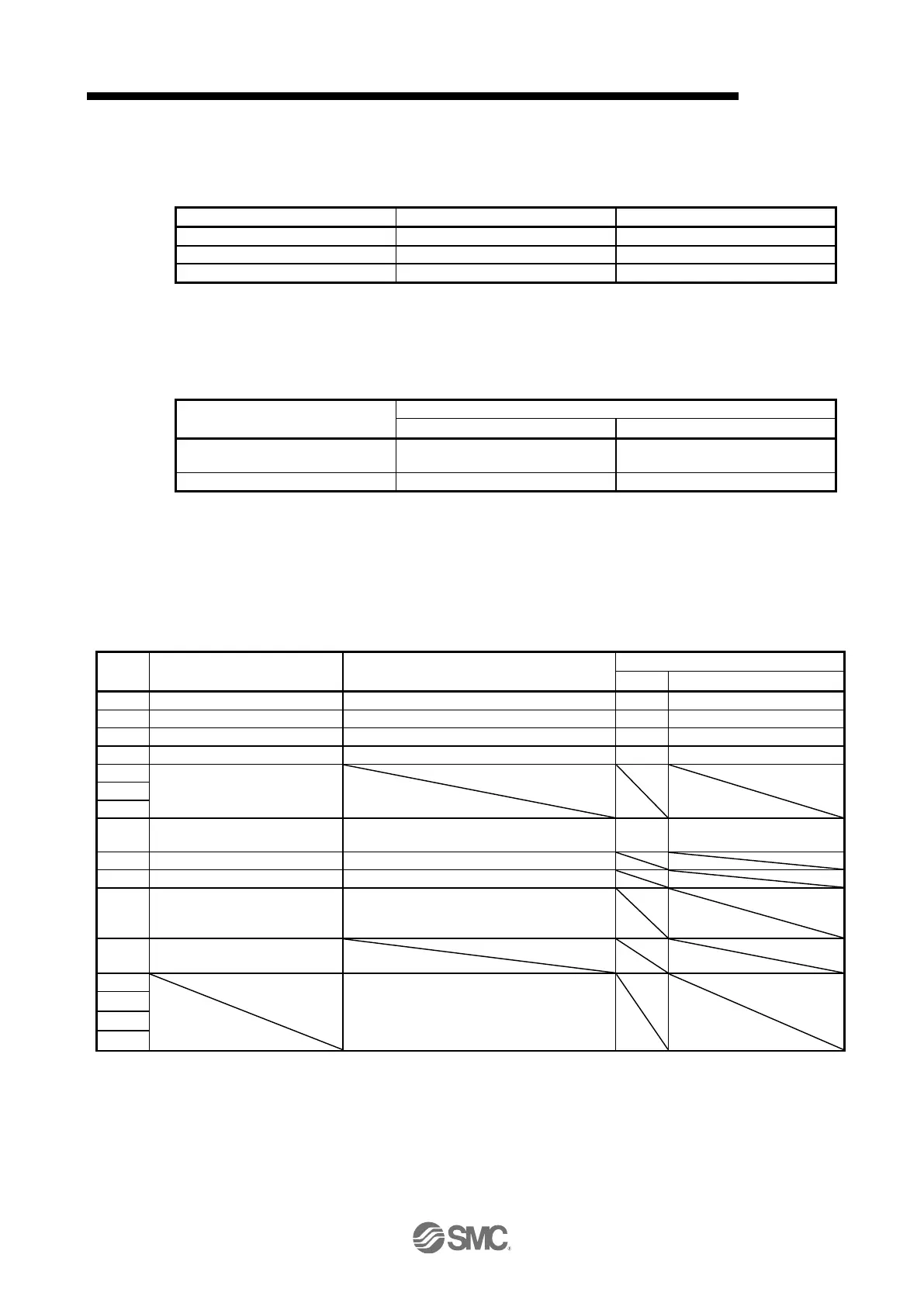
The format of Controlword/Statusword used for the ProcessData communication is different depending on
Telegrams you use.
Refer to the following table.
ProcessData communication
Control word 1 (compliant with
PROFIdrive)
Status word 1 (compliant with
PROFIdrive)
Controlword (compliant with CiA 402)
Statusword (compliant with CiA 402)
20.5.3.1 Controlword
The drive state can be switched and control commands for the functions of the drive can be issued by
rewriting Controlword from the master upper side. Refer to the followings for functions assigned to each bit.
(1) Control word 1 (compliant with PROFIdrive) bit definition
Control word 1 cannot be accessed from the Acyclic communication.
Refer to section 5.1. (Note 1)
Refer to section 5.1. (Note 1)
Refer to section 5.1. (Note 1)
Refer to section 5.1. (Note 1)
Depends on the control mode
(Refer to each control mode.)
When 1 is set from 0, alarms are reset.
(Note 1)
0: Not following PLC command (holding
previous value)
1: Drive following PLC command
Depends on the control mode
(Refer to each control mode.)
Bit 0 to 3 and 7 are used for switching drive state. Refer to chapter 5.
The values in bit 8, 9, and 12 to 15 at reading are undefined. Set "0" when writing.

 Loading...


