1. FUNCTIONS AND CONFIGURATION
1 - 22
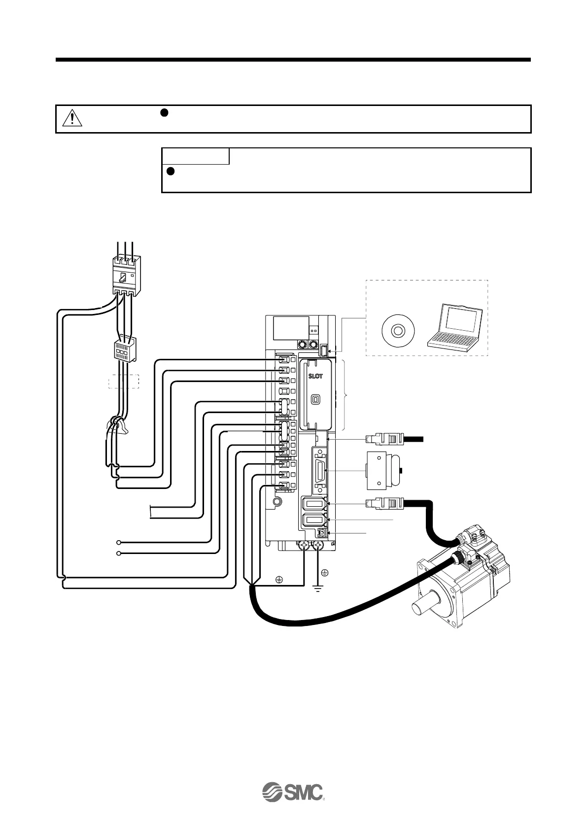
1.9 Configuration including peripheral equipment
Connecting a servo motor of the wrong axis to U, V, W, or CN2 of the driver may
cause a malfunction.
Equipment other than the driver and servo motor are optional or recommended
products.
(1) LECSN2-T□
The diagram shows LECSN2-T7.
CN4
Line noise
filter
(FR-BSF01)
CN5
Regenerative
option
P+
C
L11
L21
P3
P4
Personal
computer
MR Configurator2
Netw ork module dependence (Note 6)
CN8
CN2
CN2L (Note 4)
CN3
W
V
U
L1
L2
L3
(Note 3)
Magnetic
contactor
(MC)
(Note 1)
Power factor
improving DC
reactor
(FR-HEL)
Junction terminal
block
To safety relay or MR-J3-D05
safety logic unit
Battery
Molded-case
circuit breaker
(MCCB)
R S T
(Note 2)
Pow er supply
Servo motor
D (Note 5)
For 1-phase 200 V AC to 240 V AC, connect the power supply to L1 and L3. Leave L2 open. Refer to section 1.3 for the
power supply specifications.
Depending on the main circuit voltage and operation pattern, bus voltage decreases, and that may cause the forced stop
deceleration to shift to the dynamic brake deceleration. When dynamic brake deceleration is not required, slow the time to
turn off the magnetic contactor.
CN2L cannot be used. Connect the encoder cable to CN2.
Always connect between P+ and D terminals. When using the regenerative option, refer to section 11.2.
For the network card connections, refer to chapter 18,19,20
I/O connector
or I/O cable

 Loading...


