6. NORMAL GAIN ADJUSTMENT
6 - 13
6.3.2 Auto tuning mode basis
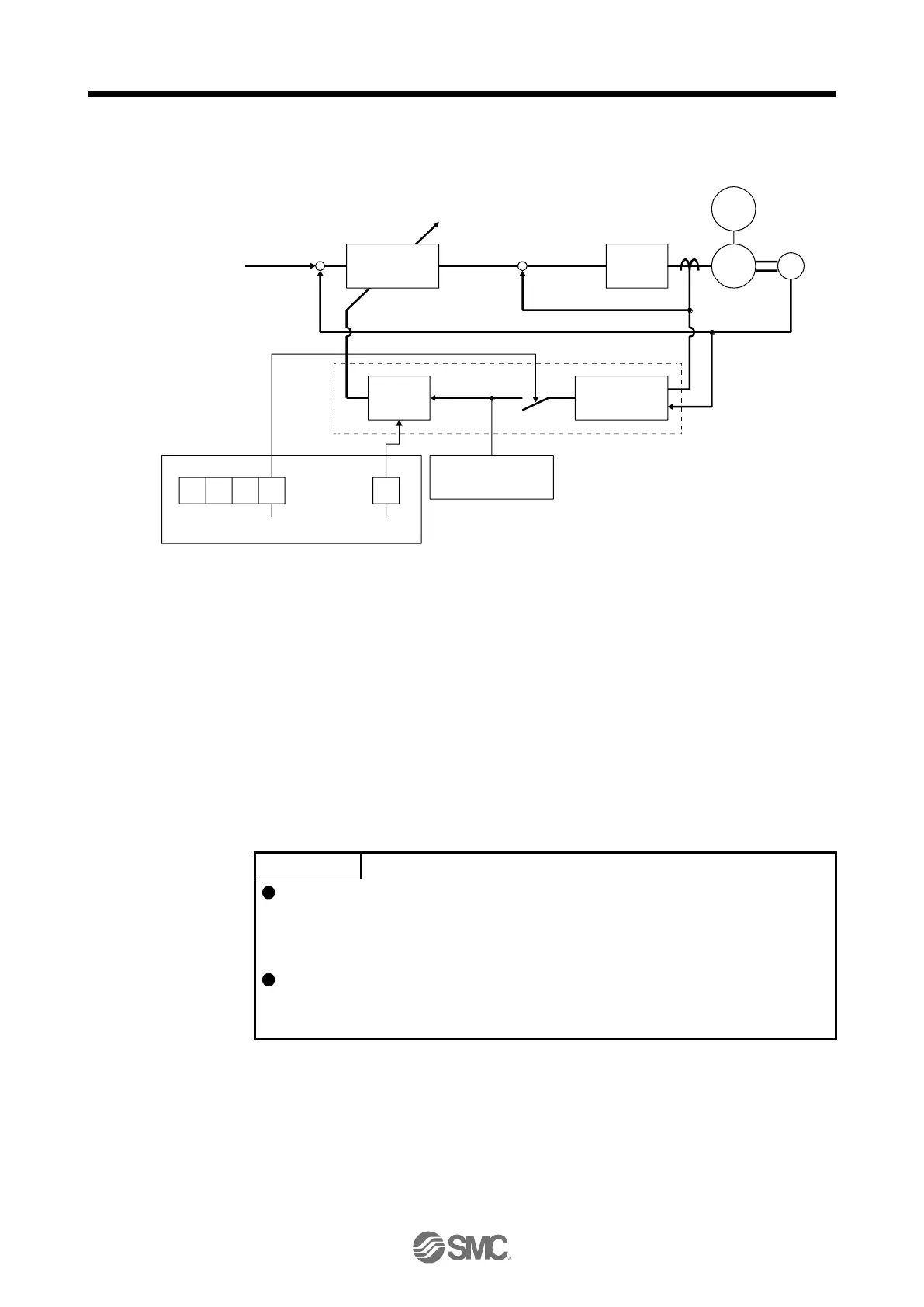
The block diagram of real-time auto tuning is shown below.
When a servo motor is accelerated/decelerated, the load to motor inertia ratio estimation section always
estimates the load to motor inertia ratio from the current and speed of the servo motor. The results of
estimation are written to [Pr. PB06 Load to motor inertia ratio]. These results can be confirmed on the status
display screen of the setup software (MR Configurator2
TM
).
If you have already known the value of the load to motor inertia ratio or failed to estimate, set "Gain
adjustment mode selection" to "Auto tuning mode 2 (_ _ _ 2)" in [Pr. PA08] to stop the estimation (turning off
the switch in above diagram), and set the load to motor inertia ratio ([Pr. PB06]) manually.
From the preset load to motor inertia ratio ([Pr. PB06]) value and response ([Pr. PA09]), the optimum loop
gains are automatically set on the basis of the internal gain table.
The auto tuning results are saved in the EEP-ROM of the driver every 60 minutes since power-on. At power-
on, auto tuning is performed with the value of each loop gain saved in the EEP-ROM being used as an initial
value.
If sudden disturbance torque is imposed during operation, the load to motor
inertia ratio may be misestimated temporarily. In such a case, set "Gain
adjustment mode selection" to "Auto tuning mode 2 (_ _ _ 2)" in [Pr. PA08] and
then set the correct load to motor inertia ratio in [Pr. PB06].
When any of the auto tuning mode 1 and auto tuning mode settings is changed
to the manual mode 2 setting, the current loop gains and load to motor inertia
ratio estimation value are saved in the EEP-ROM.

 Loading...


