11. OPTIONS AND PERIPHERAL EQUIPMENT
11 - 20
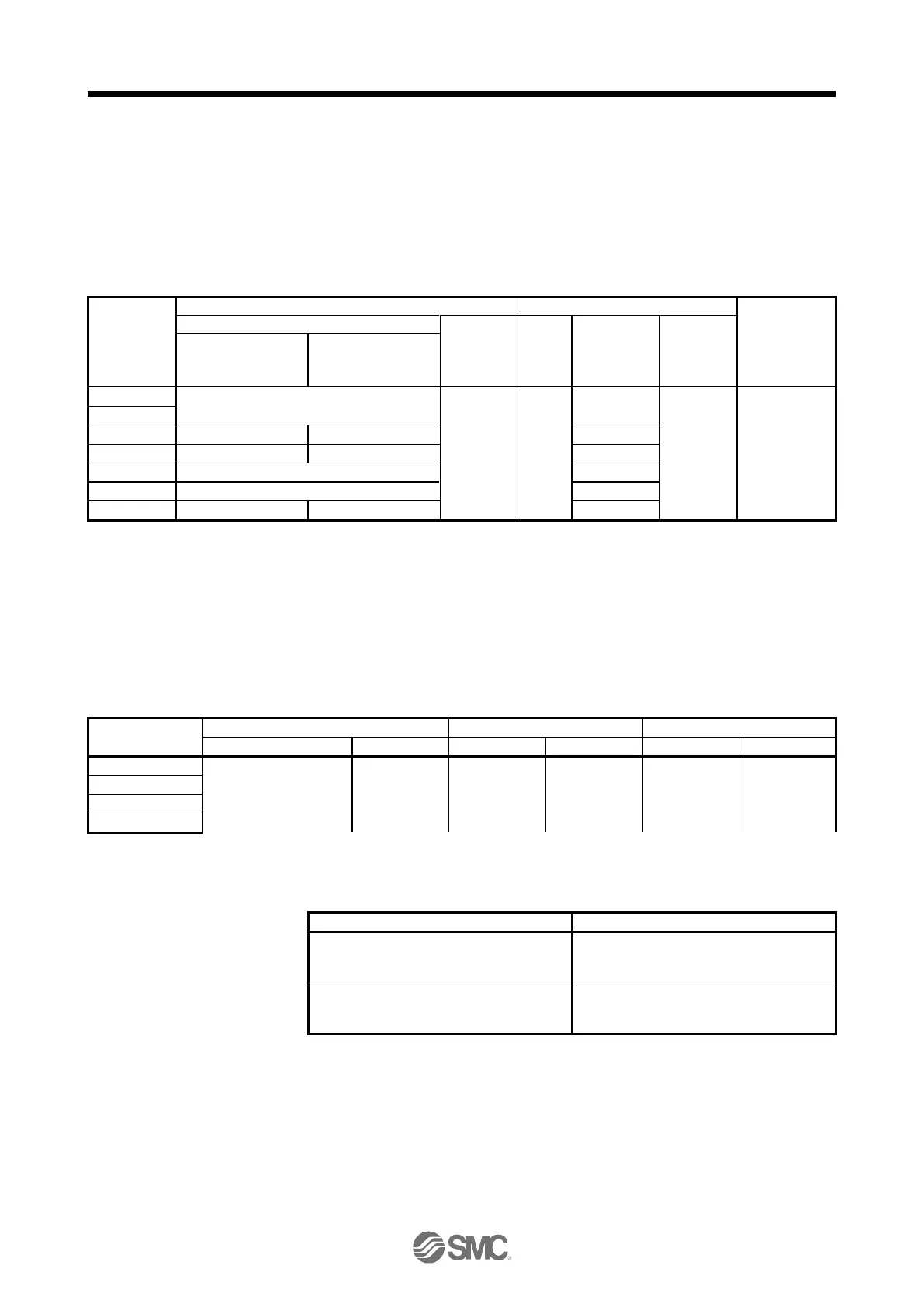
11.6 Molded-case circuit breakers, fuses, magnetic contactors (recommended)
(1) For main circuit power supply
To prevent the driver from smoke and a fire, select a molded-case circuit breaker which shuts off
with high speed.
Always use one molded-case circuit breaker and one magnetic contactor with one driver.
When using a fuse instead of the molded-case circuit breaker, use the one having the specifications
given in this section.
Molded-case circuit breaker (Note 1, 3)
Magnetic
contactor
(Note 2)
Power factor
Improving reactor is
not used
Power factor
Improving reactor is
used
S-N10
(
Mitsubishi
Electric
Corporation
)
)
When having the driver comply with the IEN/EN/UL/CSA standard, refer to app.4.
Use a magnetic contactor with an operation delay time (interval between current being applied to the coil until closure of
contacts) of 80 ms or less.
Use a molded-case circuit breaker with equal or higher operating characteristics.
(2) For control circuit power supply
When the wiring for the control circuit power supply (L11, L21) is thinner than that for the main circuit
power supply (L1, L2, L3), install an overcurrent protection device (molded-case circuit breaker or
fuse) to protect the branch circuit.
Molded-case circuit breaker
11.7 Relay (recommended)
The following relays should be used with the interfaces
Digital input (interface DI-1)
Relay used for digital input command signals
To prevent defective contacts, use a relay for
small signal (twin contacts).
(Ex.) Omron : type G2A, MY
Digital output (interface DO-1)
Relay used for digital output signals
Small relay with 12 V DC or 24 V DC of rated
current 40 mA or less
(Ex.) Omron : type MY

 Loading...


