APPENDIX
App. - 15
App. 4.8 Technical data
App. 4.8.1 LECSN2-T□ driver
LECSN2-T5 / LECSN2-T7 / LECSN2-T8 / LECSN2-T9
Main circuit (line voltage)
3-phase or 1-phase 200 V AC to 240 V AC, 50 Hz/60 Hz
Control circuit (line voltage)
1-phase 200 V AC to 240 V AC, 50/60 Hz (Note 2)
24 V DC (required current capacity: LECSN2-T□, 300 mA)
Sine-wave PWM control, current control method
Safety observation function (STO)
IEC/EN 61800-5-2 (Note 3)
EN ISO 13849-1 Category 3 PL e, IEC 61508 SIL 3,
EN 62061 SIL CL 3, and EN 61800-5-2
Mean time to dangerous failure
Effectiveness of fault monitoring of a system or
subsystem
Average probability of dangerous failures per hour
8 ms or less (STO input off → energy shut off)
1-phase 100 V AC/200 V AC: II (IEC/EN 60664-1),
3-phase 200 V AC/400 V AC: III (IEC/EN 60664-1)
Short-circuit current rating (SCCR)
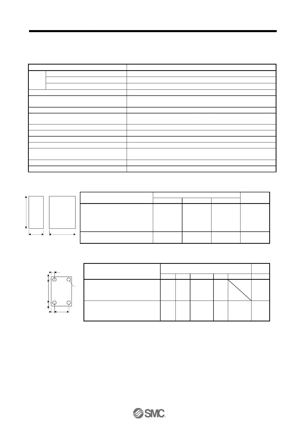
App. 4.8.2 Driver dimensions
LECSN
□
-T5 / LECSN
□
-T7/
LECSN
□
-T8
LECSN
□
-T5 / LECSN
□
-T7/
LECSN
□
-T8

 Loading...


