3. SIGNALS AND WIRING
3 - 9
3.3 Explanation of power supply system
3.3.1 Signal explanations
For the layout of connector and terminal block, refer to chapter 9.
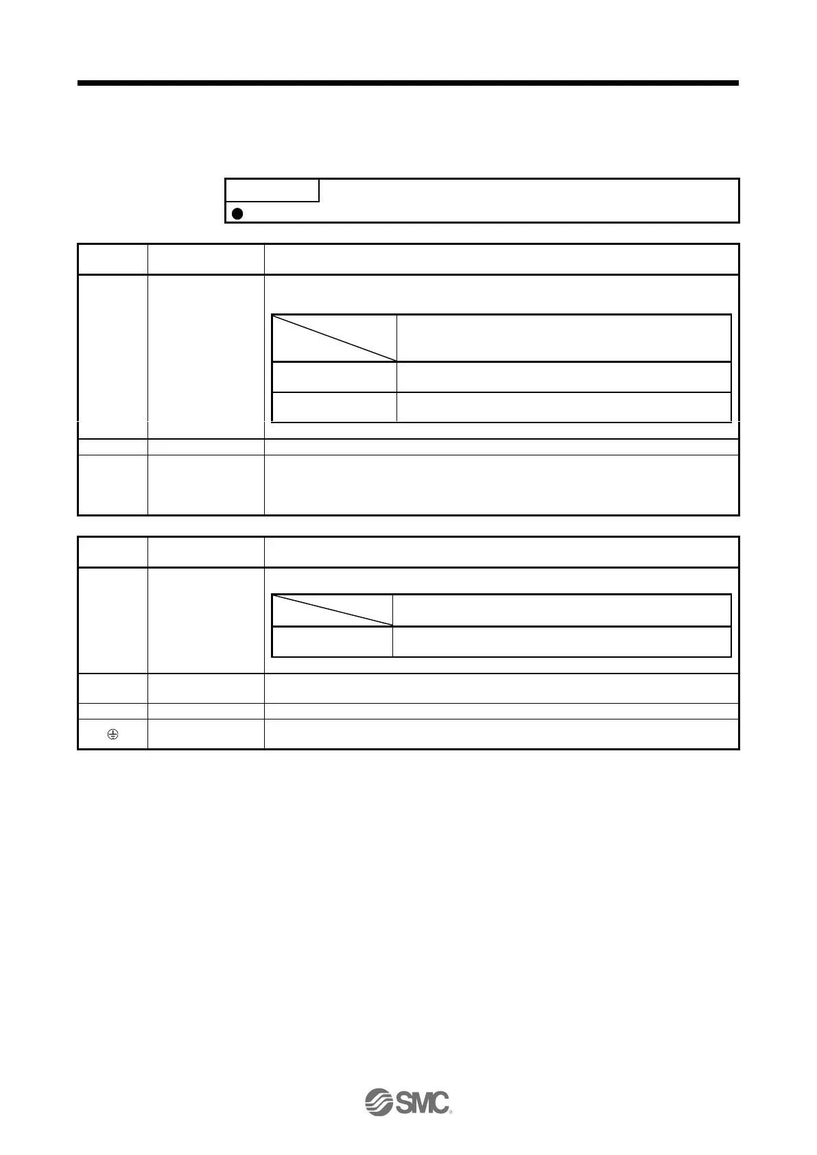
Connection target
(application)
Main circuit power
supply
Supply the following power to L1, L2, and L3. For 1-phase 200 V AC to 240 V AC, connect the
power supply to L1 and L3. Leave L2 open.
3-phase 200 V AC to
240 V AC, 50 Hz/60 Hz
1-phase 200 V AC to
240 V AC, 50 Hz/60 Hz
connect P3 and P4. (factory-wired)
When using a driver built-in regenerative resistor, connect P+ and D. (factory-wired)
When using a regenerative option, disconnect P+ and D, and connect the regenerative option to
P+ and C.
Refer to section 11.2 for details.
Connection target
(application)
Control circuit power
supply
Supply the following power to L11 and L21.
1-phase 200 V AC to
240 V AC, 50 Hz/60 Hz
Connect the driver power output (U/V/W) to the servo motor power input (U/V/W) directly. Do
not let a magnetic contactor, etc. intervene. Otherwise, it may cause a malfunction.
Connect it to the grounding terminal of the servo motor and to the protective earth (PE) of the
cabinet for grounding.

 Loading...


