11. OPTIONS AND PERIPHERAL EQUIPMENT
11 - 7
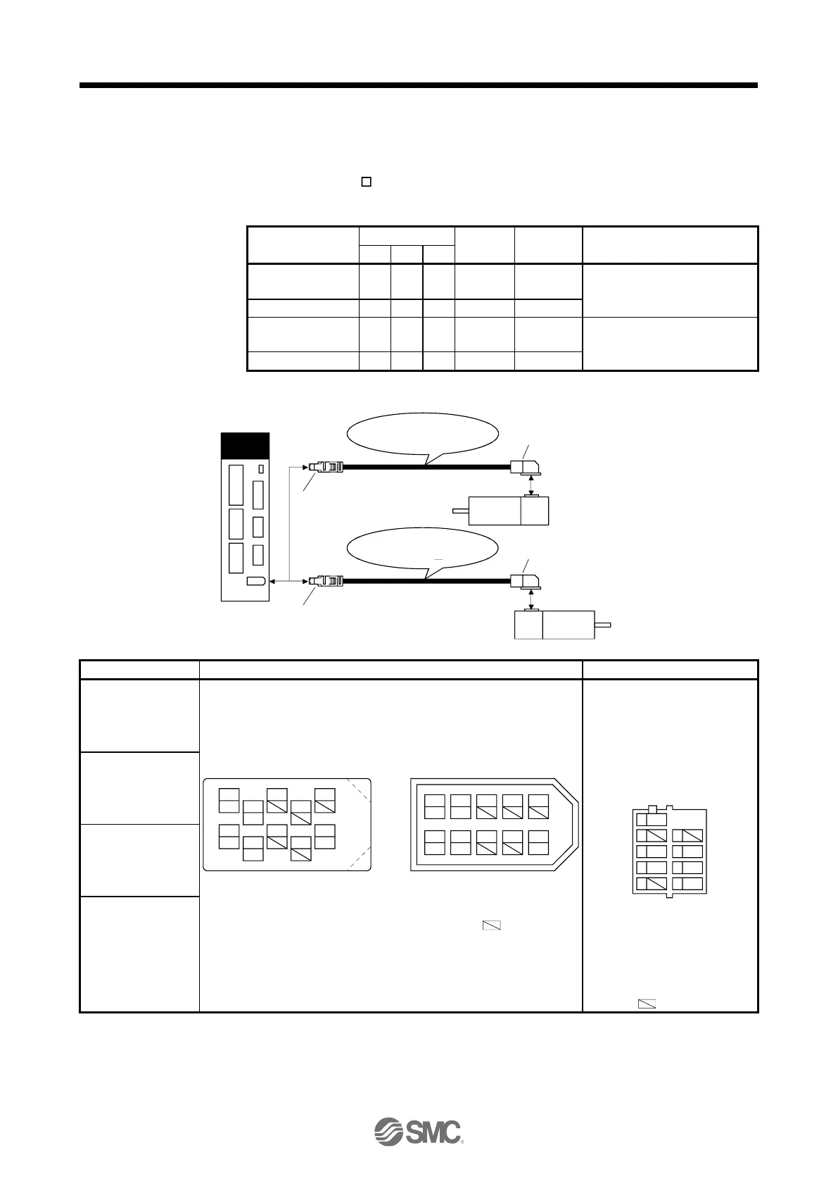
11.1.3 Encoder cable/connector sets
(1) LE-CSE- □□A・LE-CSE-□□B
These cables are encoder cables for the LE-□-□ series servo motors. The numerals in the Cable Length field
of the table are the symbols entered in the part of the cable model. The cables of the lengths with the
symbols are available.
For LE-□-□ servo motor
Axis side lead
For LE-□-□ servo motor
Counter axis side lead
(a) Connection of driver and servo motor
Servo amplifier
2)
1)
Servo motor
HF-MP
HF-KP
MR-J3ENCBL M-A2-L
MR-J3ENCBL M-A2-H
2)
1)
Servo motor
HF-MP
HF-KP
MR-J3ENCBL M-A1-L
MR-J3ENCBL M-A1-H
or
CN2
Receptacle: 36210-0100PL
Shell kit: 36310-3200-008
(Sumitomo 3M Limited)
Connector set: 54599-1019(Molex)
Connector: 1674320-1
Crimping tool for ground clip:
1596970-1
Crimping tool for receptacle
contact: 1596847-1
(Tyco Electronics)
9
SHD
7
5
MR
3
P5
1
8
6
P5G
4
MRR
2
BAT
View seen from wiring side.
(Note) Signal layout
Note. Keep open
the pin shown with
an .
1 3 7 9
42 86 10
5
(Note) Signal layout
View seen from wiring side.
or
4
MRR
2
LG
8
6
1
P5
5
10
3
MR
7
9
BAT
(Note) Signal layout
View seen from wiring side.
MRR
LG
P5 MR
BAT
Note. Keep open the pins shown with .
Especially, pin 10 is provided for manufacturer
adjustment. If it is connected with any other
pin, the driver cannot operate normally.

 Loading...


