APPENDIX
App. - 10
App. 4.4 Electrical Installation and configuration diagram
Turn off the molded-case circuit breaker (MCCB) to avoid electrical shocks or
damages to the product before starting the installation or wiring.
The installation complies with IEC/EN 60204-1. The voltage supply to machines
must be 20 ms or more of tolerance against instantaneous power failure as
specified in IEC/EN 60204-1.
Connecting a servo motor for different axis to U, V, W, or CN2_ of the driver may
cause a malfunction.
Securely connect the cables in the specified method and tighten them with the
specified torque. Otherwise, the servo motor may operate unexpectedly.
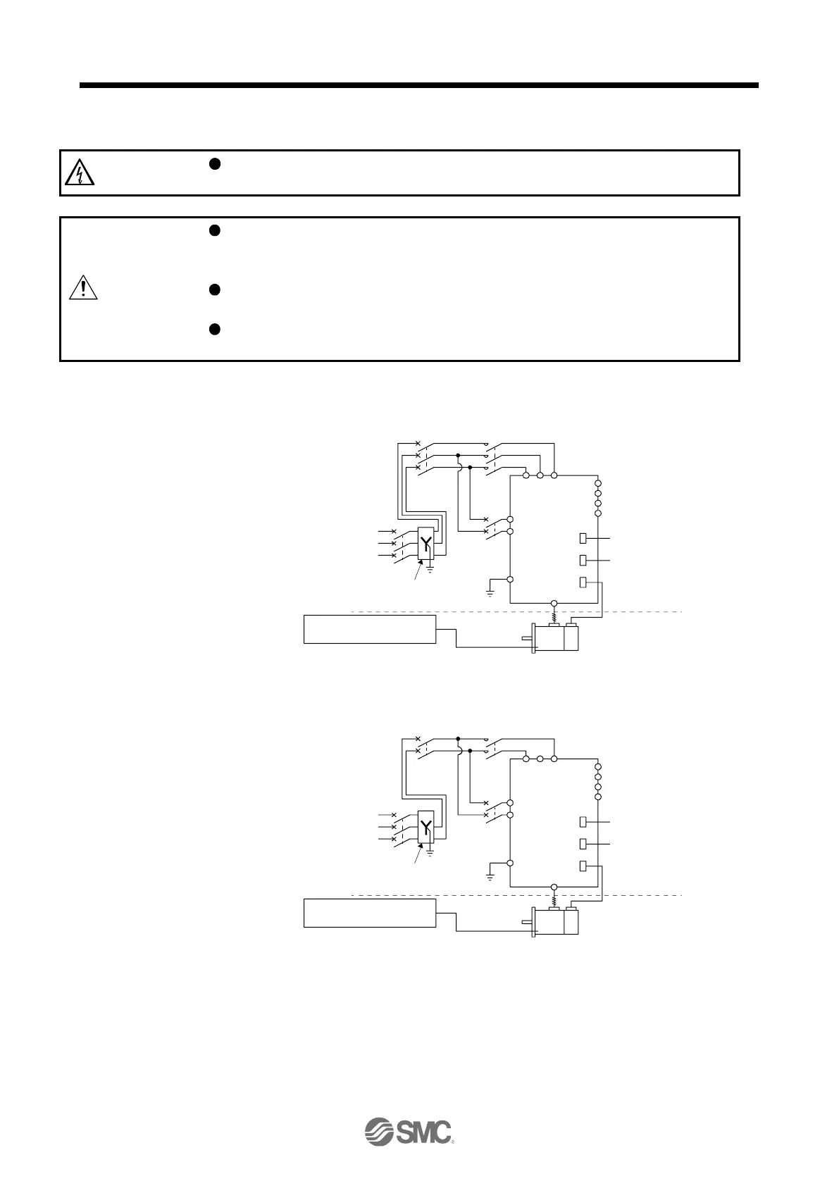
The following shows representative configuration examples to conform to the IEC/EN/UL/CSA standards.
(1) 3-phase input for LECSN2-T□ 1-axis driver
MCCB
or fuse
Controller
STO
Encoder cable
(3-phase
230 V AC)
Pow er
supply
(3-phase
400 V AC)
Transformer (Note 3)
(star-connected)
(Note 1)
MCCB
or fuse
PE
L11
L21
MC
Servo amplifier
Cabinet side
Machine side
Encoder
Servo motor
L1
C
P+
D
N-
U/V/W/PE
CN2
CN1
CN8
L2L3
To protective equipment
(Thermal signal) (Note 2)
When the wire sizes of L1 and L11 are the same, MCCB or fuse is not required.
Please use a thermal sensor, etc. for thermal protection of the servo motor.
(2) 1-phase input for LECSN2-T□ 1-axis driver
MCCB
or fuse
Controller
STO
Encoder cable
(1-phase
230 V AC)
Pow er
supply
(3-phase
400 V AC)
Transformer
(star-connected)
(Note 1)
MCCB
or fuse
PE
L11
L21
MC
Servo amplifier
Cabinet side
Machine side
Encoder
Servo motor
L1
C
P+
D
N-
U/V/W/PE
CN2
CN1
CN8
L2L3
(Note 2)
(Note 2)
To protective equipment
(Thermal signal) (Note 3)
When the wire sizes of L1 and L11 are the same, MCCB or fuse is not required.
When using a 100 V class driver, step down the power supply voltage to 100 V
and connect the main circuit power supply lines to L1 and L2. For 1-phase 200 V
AC drivers, connect the lines to L1 and L3.

 Loading...


