5. PARAMETERS
5 - 100
5.4 How to set the electronic gear
5.4.1 Electronic gear setting in the cyclic synchronous mode, profile mode and point table method
The position data unit that can be set vary depending on the control mode.
Refer to [Pr. PT01 Position data unit] for details.
(1) Setting [mm], [inch], or [pulse] with "Position data unit" of [Pr. PT01]
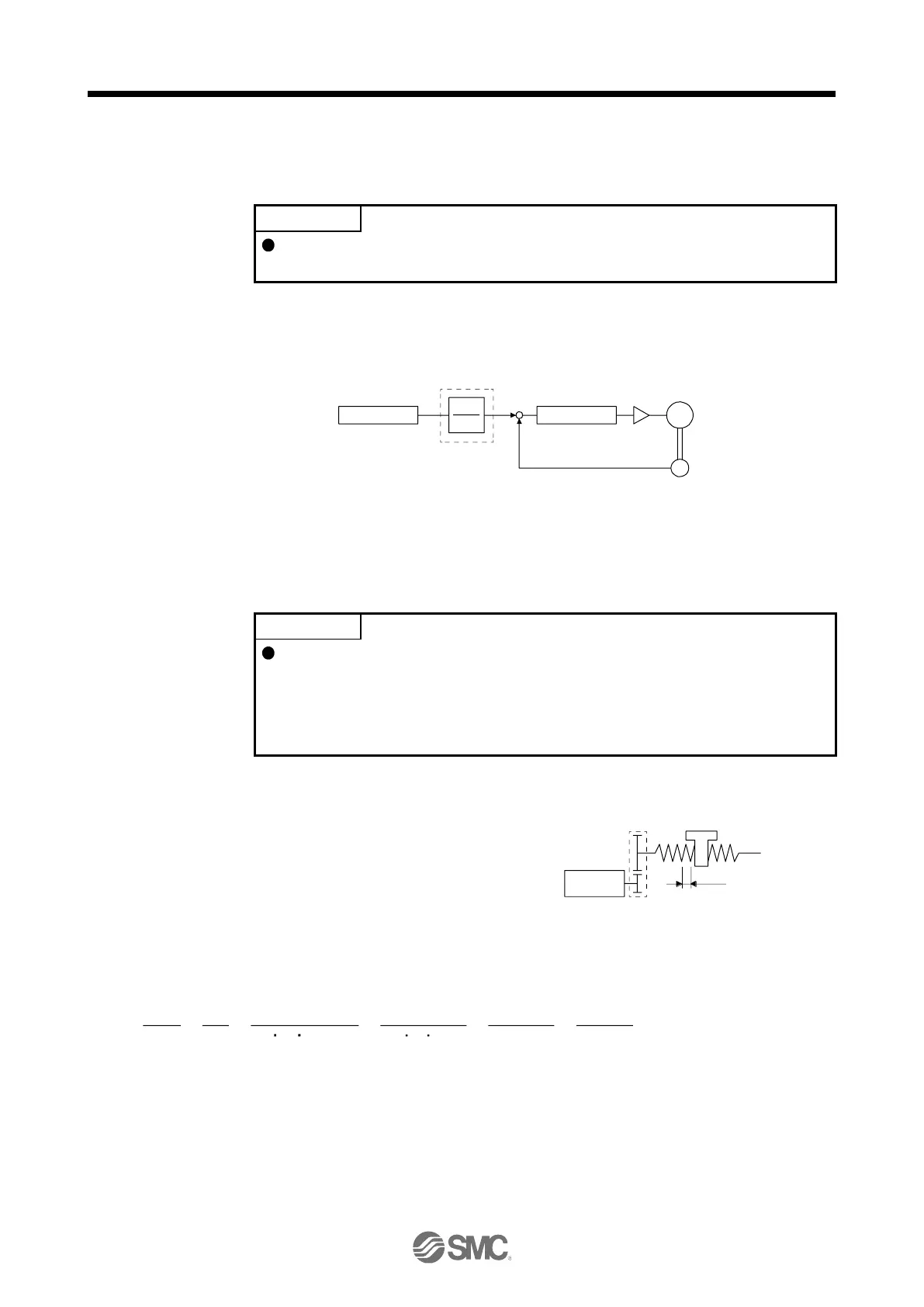
Adjust [Pr. PA06] and [Pr. PA07] to match the driver setting with the travel distance of the machine.
Travel distance
CDV
CMX
Deviation counter
+
-
Electronic gear
([Pr. PA06]/[Pr. PA07])
Servo motor
Encoder
M
P
t
: Servo motor encoder resolution: 4194304 [pulse/rev]
ΔS: Travel distance per servo motor revolution [mm/rev]/[inch/rev]/[pulse/rev]
CMX/CDV = P
t
/ΔS
The following setting example explains how to calculate the electronic gear.
To calculate the electronic gear, the following specification symbols are required.
Pb: Ball screw lead [mm]
1/n: Reduction ratio
P
t
: Servo motor encoder resolution [pulse/rev]
ΔS: Travel distance per servo motor revolution [mm/rev]
(a) Setting example of a ball screw
Machine specifications
Ball screw lead Pb = 10 [mm]
Reduction ratio: 1/n = Z
1
/Z
2
= 1/2
Z
1
: Number of gear teeth on servo motor side
Z
2
: Number of gear teeth on load gear
Servo motor encoder resolution
4194304 [pulse/rev]
Pb = 10 [mm]
Z1
1/n = Z1/Z2 = 1/2
Z2
1/n
Servo motor encoder resolution P
t
= 4194304 [pulse/rev]
1/n Pb α (Note)
CMX
CDV
P
t
=
ΔS
P
t
=
4194304
=
4194304
=
5000
524288
=
6251/2 10 1000
Because the command unit is "mm", α is 1000. When the unit is "inch", α is 10000. When the unit is "pulse", α is 1.
Therefore, set CMX = 524288 and CDV = 625.

 Loading...


