4. STARTUP
4 - 7
4.3 Switch setting and display of the driver
For EtherNet/IP and PROFINET, an IP address is displayed in the digit of the
axis number.
Switching to the test operation mode and setting control axis No. are enabled with switches on the driver.
On the driver display (three-digit, seven-segment LED), check the status of communication with the upper
side at power-on, and the axis number, and diagnose a malfunction at occurrence of an alarm.
4.3.1 Switches
When switching the axis selection rotary switch (SW2/SW3) and mode select
switch (SW1), use insulated screw driver. Do not use a metal screw driver.
Touching patterns on electronic boards, lead of electronic parts, etc. may cause
an electric shock.
Turning "ON (up)" all the mode select switches (SW1) enables an operation
mode for manufacturer setting and displays "off". The mode is not available. Set
the mode select switches (SW1) correctly according to this section.
Cycling the main circuit power supply and control circuit power supply enables
the setting of each switch.
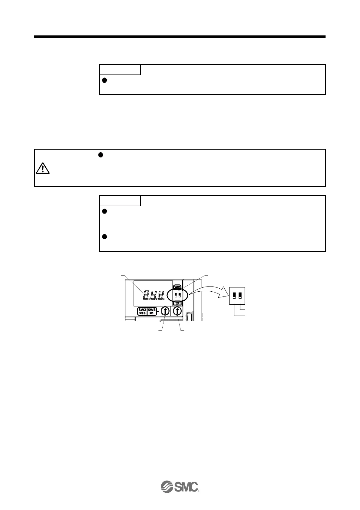
The following explains the mode select switches (SW1) and the axis selection rotary switch.
3-digit, 7-segment LED
Axis selection rotary sw itch (upper) (SW2) Axis selection rotary sw itch (lower) (SW3)
Mode select sw itch (SW1)
1
ON
2
1
ON
2
For manufacturer setting (SW1-2)
Test operation select sw itch (SW1-1)
(1) Test operation select switch (SW1-1)
To use the test operation mode, turn "ON (up)" the switch. Turning "ON (up)" the switch enables the test
operation mode. In the test operation mode, the functions such as JOG operation, positioning operation,
and machine analyzer are available with Setup software (MR Configurator2
TM
)
(2) Axis selection rotary switch (SW2/SW3)
Control axis No. of the servo can be set. For the settings, refer to chapter 18,19,20.

 Loading...


