20.PROFINET COMMUNICATION
Table 5.2 State transition
The control circuit power supply is turned on.
The state automatically transitions when the control circuit power
supply is turned on.
The state transitions with the Shutdown command from the
master.
The state transitions with the Switch on command from the
master.
The state transitions with the Enable operation command from
the master.
The operation becomes ready after servo-on.
The state transitions with the Disable operation command from
the master.
The operation is disabled after servo-off.
The state transitions with the Shutdown command from the
master.
The state transitions with the Disable Voltage command or Quick
Stop command from the master.
(a) The state transitions with the Shutdown command from the
master.
(b) The state transitions when the main circuit power supply is
turned off.
Operation is disabled after servo-off or RA-off.
The state transitions with the Disable Voltage command from the
master.
Operation is disabled after servo-off or RA-off.
The state transitions with the Disable Voltage command or Quick
Stop command from the master.
The state transitions with the Quick Stop command from the
master.
(a) The state automatically transitions after Quick Stop is
completed. (If the Quick Stop option code is 1, 2, 3, or 4)
(b) The state transitions with the Disable Voltage command from
the master.
Operation is disabled after servo-off or RA-off.
Processing against the alarm is executed.
After processing against the alarm has been
completed, servo-off or RA-off is performed and
the operation is disabled.
The state transitions with the Fault Reset command from the
master.
Alarms are reset. Resettable alarms are cleared.
The state transitions with the Enable Operation command from
the master. (If the Quick Stop option code is 5, 6, 7, or 8)
The operation becomes ready. (Not supported)
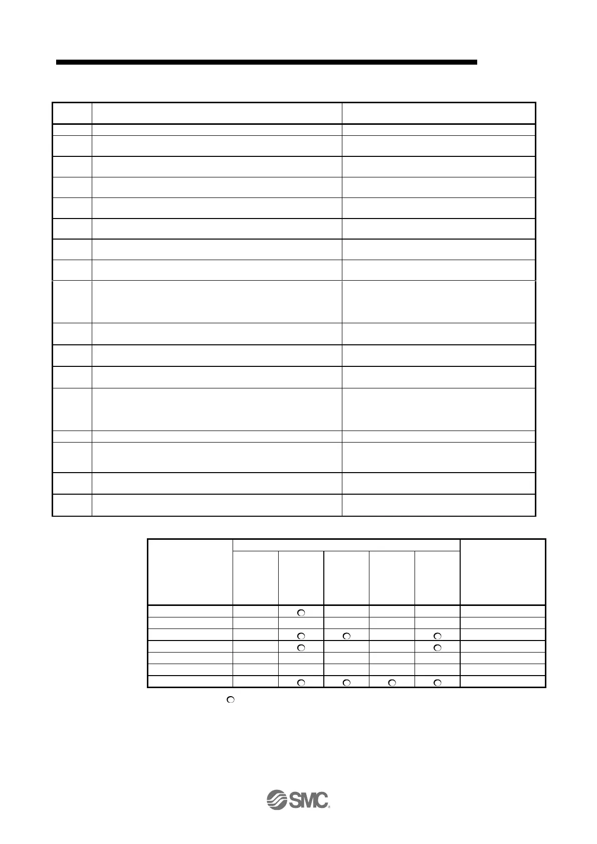
Correspondence relation between command bit setting and FSA state transition
Command bit setting of Controlword (Note)
0: OFF 1: ON : ON/OFF
In faulty communication, hold the state of Bit 7 = 1 for as follows for the Fault Reset command to prevent
the command from failing to be recognized.
10 ms ≥ twice the communication cycle: Hold the state for 10 ms.
10 ms < twice the communication cycle: Hold the state for the time determined by doubling the
communication cycle.

 Loading...


