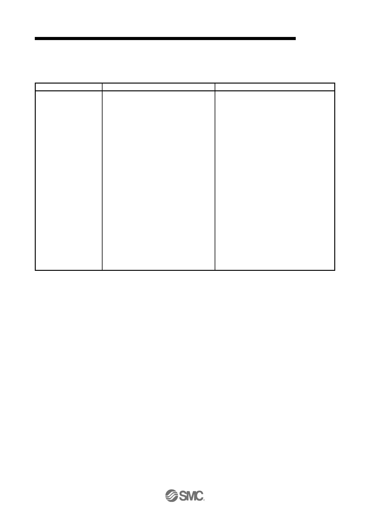
(2) I/O communication format (output)
The following table lists the communication data formats from slaves (driver) to the master (upper side).
Instance numbers in the table correspond to the instance numbers of Assembly object.
1 Byte: Modes of operation display (6061h)
1 Byte: Reserved
2 Byte: Statusword (6041h)
4 Byte: Position actual value (6064h)
4 Byte: Velocity actual value (606Ch)
2 Byte: Torque actual value (6077h)
2 Byte: Reserved
4 Byte: Reading data
2 Byte: Respond code
2 Byte: Status DO 10 (2D1Ah)
2 Byte: User defined data 0 (Initial value: Status
DO 1 (2D11h)) (Note)
2 Byte: User defined data 1 (Initial value: Status
DO 2 (2D12h)) (Note)
2 Byte: User defined data 2 (Initial value: Status
DO 3 (2D13h)) (Note)
2 Byte: Reserved
4 Byte: User defined data 3 (Initial value:
Following error actual value (60F4h))
(Note)
4 Byte: User defined data 4 (Initial value: Digital
Input (60FDh)) (Note)
4 Byte: User defined data 5 (Initial value: Not
assigned) (Note)
4 Byte: User defined data 6 (Initial value: Not
assigned) (Note)
16 Byte: Reserved
Profile position mode (pp)
Profile velocity mode (pv)
Profile torque mode (tq)
Homing mode (hm)
Mapping for an application in which the modes
above are switched
Map size: 64 bytes
(3) Variable mapping function
The instances defined by User defined data_ can be dynamically switched to any send instance or
receive instance. Use instruction codes for switching instances. Refer to section 6.2 for details.

 Loading...


