RM0440 Rev 4 1213/2126
RM0440 Advanced-control timers (TIM1/TIM8/TIM20)
1226
28.6.23 TIMx capture/compare mode register 3
(TIMx_CCMR3)(x = 1, 8, 20)
Address offset: 0x050
Reset value: 0x0000 0000
Refer to the above CCMR1 register description. Channels 5 and 6 can only be configured in
output.
Bits 31:20 Reserved, must be kept at reset value.
Bits 19:0 CCR6[19:0]: Capture/compare 6 value
CCR6 is the value to be loaded in the actual capture/compare 6 register (preload value).
It is loaded permanently if the preload feature is not selected in the TIMx_CCMR3 register
(bit OC6PE). Else the preload value is copied in the active capture/compare 6 register when
an update event occurs.
The active capture/compare register contains the value to be compared to the counter
TIMx_CNT and signaled on tim_oc6 output.
Non-dithering mode (DITHEN = 0)
The register holds the compare value in CCR6[15:0]. The CCR6[19:16] bits are reset.
Dithering mode (DITHEN = 1)
The register holds the integer part in CCR6[19:4]. The CCR6[3:0] bitfield contains the
dithered part.
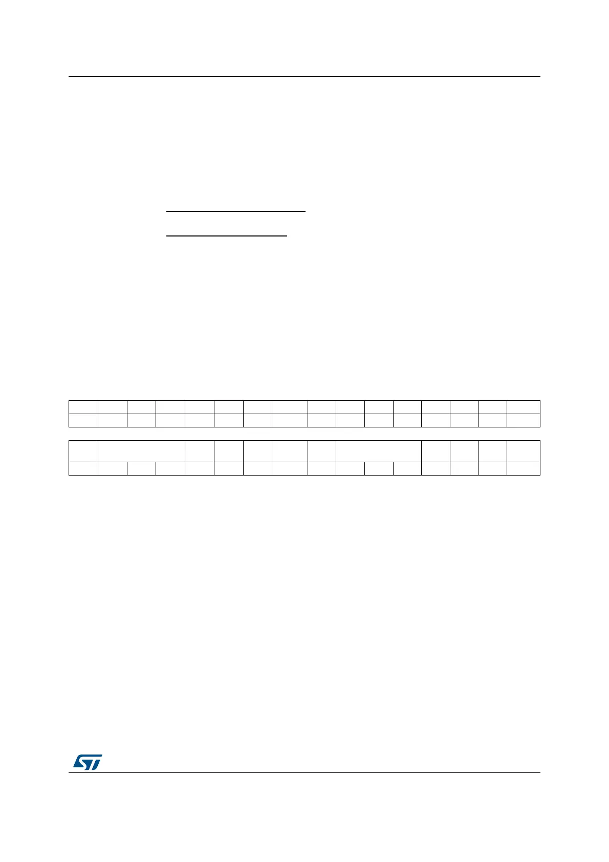
31 30 29 28 27 26 25 24 23 22 21 20 19 18 17 16
Res. Res. Res. Res. Res. Res. Res. OC6M[3] Res. Res. Res. Res. Res. Res. Res. OC5M[3]
rw rw
1514131211109 8 7654321 0
OC6
CE
OC6M[2:0]
OC6
PE
OC6FE Res. Res.
OC5
CE
OC5M[2:0] OC5PE OC5FE Res. Res.
rw rw rw rw rw rw rw rw rw rw rw rw
Bits 31:25 Reserved, must be kept at reset value.
Bits 23:17 Reserved, must be kept at reset value.
Bit 15 OC6CE: Output compare 6 clear enable
Bits 24, 14:12 OC6M[3:0]: Output compare 6 mode
Bit 11 OC6PE: Output compare 6 preload enable
Bit 10 OC6FE: Output compare 6 fast enable
Bits 9:8 Reserved, must be kept at reset value.
Bit 7 OC5CE: Output compare 5 clear enable
Bits 16, 6:4 OC5M[3:0]: Output compare 5 mode
Bit 3 OC5PE: Output compare 5 preload enable
Bit 2 OC5FE: Output compare 5 fast enable
Bits 1:0 Reserved, must be kept at reset value.
 Loading...


