63
(1) Open the [SETUP > BUS LINK > BUS LINK] menu PAGE 2.
(2) Set MASTER BUS to M/E1PGM and SLAVE BUS to M/E1PST as shown below.
(3) Set LINK MODE to NORMAL.
SETUP > BUS LINK > BUS LINK
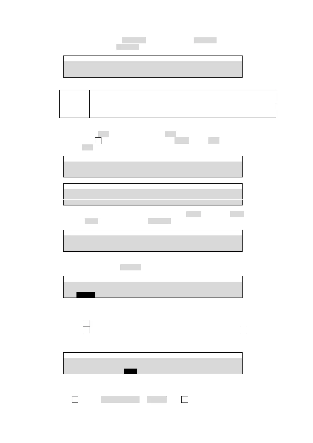
LINK MODE Setting
When the video image is changed in a Master Bus, the paired image is
automatically applied to its Slave Bus.
When the video image is changed in a Master Bus, the same image is
automatically applied to its Slave Bus.
(4) Go to PAGE 3. Select pair images for LINK1.
(a) Select IN01 for MASTER XPT, and IN05 for SLAVE XPT.
(b) Turn F2 to change the pair number to No.02. Select IN02 for MASTER XPT, and
IN06 for SLAVE XPT.
SETUP > BUS LINK > BUS LINK
SETUP > BUS LINK > BUS LINK
(5) Go back to PAGE 2. Change the link number to LINK2, and select AUX1 for MASTER
BUS, AUX2 for SLAVE BUS and NORMAL for LINK MODE.
SETUP > BUS LINK > BUS LINK
(6) Refer to Step (4) to select pair images for LINK2.
(7) Then turn BUS LINK ENABLE to enable all bus (video) links in PAGE 1.
SETUP > BUS LINK > BUS LINK
Copying BUS LINK Setting
(1) Open [SETUP > BUS LINK > BUS LINK] menu PAGE 4.
(2) Turn F1 to select a destination link number (LINK3, for example).
(3) Turn F2 to select a source link number (LINK1, for example), then press F2. Select YES
in the confirmation dialog.
LINK1 setting is copied to LINK3.
SETUP > BUS LINK > BUS LINK
Resetting Bus Links
(1) Open [SETUP > BUS LINK > BUS LINK] menu PAGE 4.
(2) Turn F3 to select CURRENT LINK or ALL INIT, then F3.