05/2014
6-201
DC SC2020
General
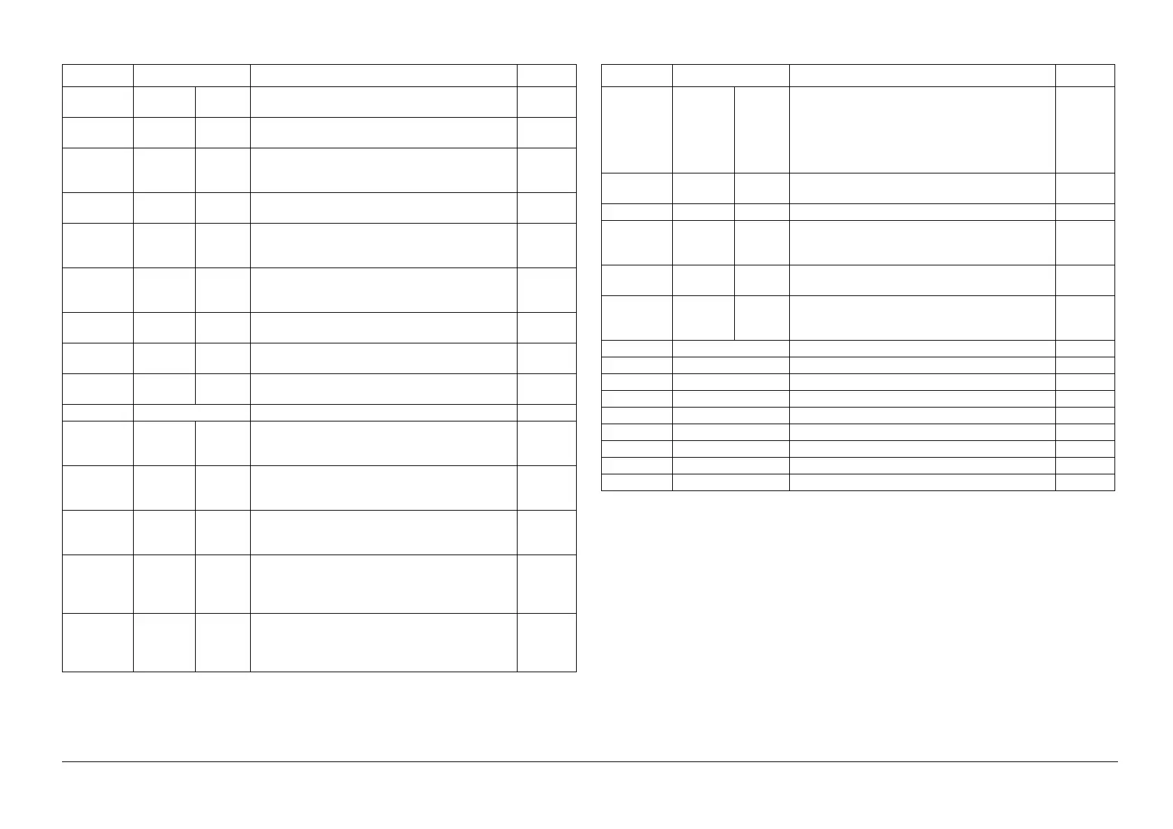
6.4.6 CE Mode Functions Overview
Version 1.1
Relay/Sig-
nal Test
Relay
Test
Toggles the Relay signal at the specified frequency. 6.4.14.5
Hook
Test
Toggles the Hook signal at the specified frequency. 6.4.14.5
Single
Tone
Send
Continuously sends the tone at the selected fre-
quency.
6.4.14.5
DTMF
Send
Continuously sends the DTMF signal. 6.4.14.5
Dial
Pulse
Send
Sends the multi-digits Dial Pulse (10/20pps) signal. 6.4.14.5
Ring
Back
Tone
Sends the ringback tone. 6.4.14.5
Data
Send
Specifies the speed and pattern for checking data
forwarding(no pattern for V.34)
6.4.14.5
Line Volt-
age
Checks the status of the Line Voltage. 6.4.14.5
Line Cur-
rent
Checks the status of the Line Current. 6.4.14.5
Information Scan Counter Displays the Scan counter value. 6.4.15.1
Scanner
Maintenance
Scan
Counter
Clear
Counter
Clear
(FB)
Clears the number of times were scanned using the
Platen.
6.4.16.1
Counter
Clear
(DADF)
Clears the number of times were scanned using the
DADF.
6.4.16.1
Auto Shad-
ing
(Ready to
Start)
(Platen) Performs auto correction for the White Ref-
erence Board’s uneven density and degradation due
to the passage of time.
6.4.16.2
CVT Auto
Shading
(Color)
(Ready to
Start)
This diagnostic function performs correction on the
density dispersion that is caused by floating DADF.
Scans in Color and calculates the Color Density
Coefficient.
6.4.16.3
CVT Auto
Shading
(Gray)
(Ready to
Start)
This diagnostic function performs correction on the
density dispersion that is caused by floating DADF.
Scans in Gray and calculates the Gray Density Coef-
ficient.
6.4.16.4
Table 2 Function Names and Details (Fax/Scanner)
Function Description See
LED Cali-
bration
(Ready to
Start)
Performs correction on the dispersion that is caused
by the LED lamp color sensitivity. Calculates a* and
b* from the Y Patch scan value of Calibration Chart
(STP5001) and then compares them with reference
values that were pre-set in the NVM to select the
Correction Coefficient No. to set in the NVM.
6.4.16.5
Componet
Check
IIT Input Digital Input Checks the status of the IIT sensor. 6.4.16.6
IIT Output Digital Output Checks the status of the motor drive. 6.4.16.6
DADF
Componet
Check
DADF IIT
Input
Digital Input Checks the status of the DADF sensor. 6.4.16.7
DADF IIT
Output
Digital Output Checks the status of the motor drive. 6.4.16.7
DADF Size
Detect
Auto Adj.
(Ready to
Start)
Performs troubleshooting for the IIT and displays the
presumed Faulty Parts No. on the UI.
6.4.16.8
Parameter Chain Link Specifies the system data setting using ChainLink. 6.4.17
BackupData All Clear Deletes the SRAM/EEPROM backup data. 6.4.18
User Clear Deletes the SRAM/EEPROM backup data. 6.4.18
Sysytem Clear Deletes the SRAM/EEPROM backup data. 6.4.18
User&Sysytem Clear Deletes the SRAM/EEPROM backup data. 6.4.18
System Data Init Deletes the SRAM/EEPROM backup data. 6.4.18
Document Clear Deletes the document data in the Fax Flash Memory. 6.4.18
DADF Clear Deletes the DADF data . 6.4.18
Complete Complete Exits the CE mode and restarts the MPF. 6.4.4
Table 2 Function Names and Details (Fax/Scanner)
Function Description See
 Loading...