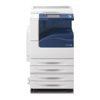
7.3.1 Preface
7-1 7.3 BSD (Block Schematic Diagram)
7.3.1 Preface
7.3.1.1 How to Use the BSDs
1. Enter the Chain specified in the Troubleshooting chapter.
2. Or enter the appropriate Chain, referring to the Contents.
3. Perform failure analysis in the Chain, using test data and
the general procedures in the General chapter.
4. Once you have located the failure, go to the Parts List No.
and/or Adjustment No. indicated for reference on the
BSD.
Warning Before installing or removing parts, switch off
the main power switch and disconnect the
power cord from the outlet to avoid possible
electric shocks or injuries.
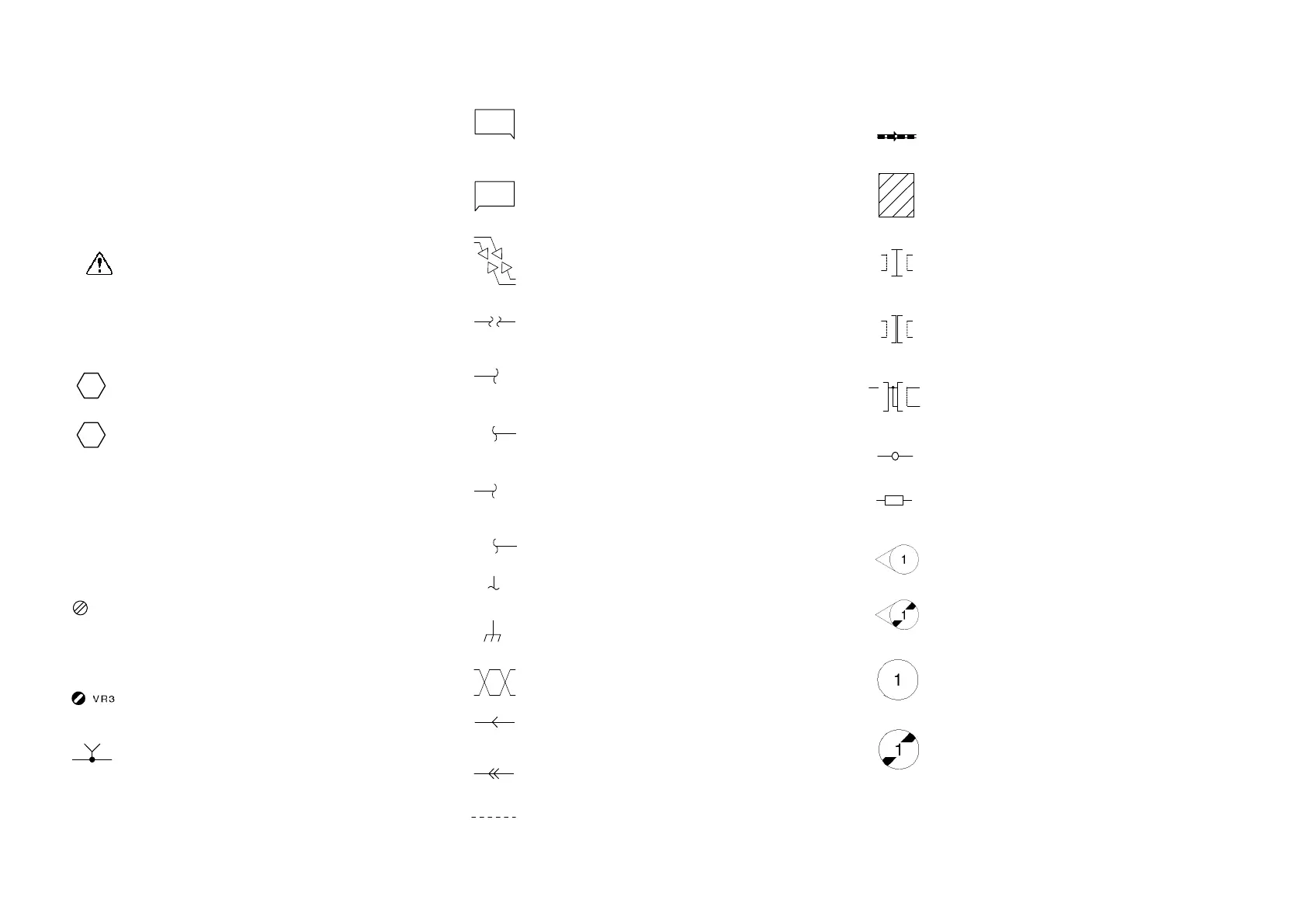
7.3.1.2 Explanation of Symbols
Refers to the note that is usually on the same page.
Refers to test data that is usually on the same page
when the voltage value shown on the BSD is different
from the measured value.
Refers to the Parts List No. PL stands for Parts List.
7.7 refers to the Plate No. PL No. indicates that the
part is listed on the specified plate.
PL No. is shown for all the replaceable parts on the
BSDs.
Refers to the adjustment item(s) in the Disassembly,
Assembly, and Adjustment chapter. 7.7.1 indicates that
the adjustment procedure is described under the 7.7.1
section in the Disassembly, Assembly, and Adjustment
chapter.
Indicates a variable register that is adjustable in the field.
Indicates a signal test point.
Indicates where the input to a function originates. The
example indicates that the input originates from group
function 3 of Chain 1
Indicates where the output from a function goes. The
example indicates that the output goes to group function
1 of chain 6.
Indicates that the signal line continues vertically.
Indicates that the signal line continues horizontally.
Indicates that the signal line goes to another zone in
the same function. The example refers to zone E3.
Indicates that the signal line goes back to another zone
in the same function. The example refers to zone A4
Indicates that the signal line goes to a zone in another
sheet. The example refers to zone A2, CH8.5.
Indicates that the signal line goes back to a zone in
another sheet. The example refers to zone H4, CH8.5.
Indicates a power line output from Chain 1.
Indicates frame ground.
Indicates a twisted pair of wires.
Indicates that the signal goes from right to left, in the
opposite direction to the normal direction.
Indicates a feedback signal.
Indicates a mechanical connection to a part.
Indicates that a mechanical drive signal goes in the
direction indicated.
Indicates Control Logic.
Indicates a double plug connector.
Indicates a drawer connector.
Indicates a shorting plug connector.
Indicates that the fasten is used for connection.
Indicates that an electrically conductive material such
as a leaf spring and a plate is used for connection.
Indicates that the symbol-pointed-to section has been
modified to code 1V.
Indicates the symbol-pointed-to section has not been
modified to code 1V.
Indicates that the whole figure or the framed illustration
has information with 1V installed.
Indicates that the whole figure or the framed illustration
has information without 1V installed.
PL7.7
ZONE
E3
ZONE
A4
CH8.5
ZN A2
CH8.5
ZN H4
P11
1
2
J11
2
1
P11
1
2
J11
2
1
TD
1
1
7.7.1
A B
A B
TP1
1.3
6.1
+5VDC
(1.2 J2)
J880B
4
J880A
3
1
 Loading...