7-2 7.3 BSD (Block Schematic Diagram)
7.3.1 Preface
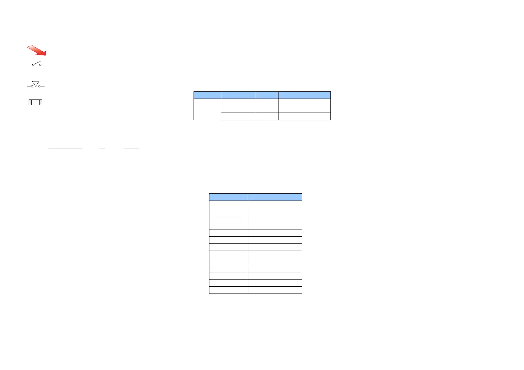
Indicates direction the air flows.
Indicates switch and is also used as Interlock Switch.
Indicates the Cheater type of Interlock Switch.
Indicates the Chip Fuse.
7.3.1.3 Signal Name
Signal name structure
・ Input component
PAPER SENSED
(L) +5VDC
Operation state Logical value Voltage with signal (H)
The example indicates that when paper is sensed, this
signal level is (L) and that otherwise, the signal level is (H)
with the voltage +5VDC.
・ Output components
ON
(L) +24VDC
Operation state Logical value Voltage with signal (H)
The example indicates that when the part is ON, the signal
level is (L) and that when it is OFF, the signal level is (H) with
the voltage +24VDC.
7.3.1.4 DC Voltage
A measurement of DC voltage is made between the particular
test point and the frame unless otherwise specified by note
and test data. The measured DC voltage is in the range
below:
LVPS Voltage Level Range
LVPS
+5VDC
(Always On)
(H)
+4.75~+5.25VDC
+24VDC
(H)
+22.8~+25.2VDC
7.3.1.5 Other Descriptions
Input Component Voltage Level
The voltage levels (H/L) shown on the BSDs are the levels that
are measured by the tester. Some of them are therefore
different from H/L displayed on the UI panel.
Wiring Color
Wires are distinguished by color in part of the BSDs for this
model. The colors of wires are shown below the signal lines
in their respective abbreviations listed below:
Abbreviation Color
BRN BROWN
RED RED
ORN ORANGE
YEL YELLOW
GRN GREEN
BLU BLUE
VIO VIOLET
GRY GRAY
WHT WHITE
BLK BLACK
GRN/YEL GREEN/YELLOW
PNK PINK
SKY SKY
Figures on the BSDs
The grayed-out portion of the figure shows the path from Motor
or Solenoid to parts to drive.
 Loading...