Home
HP
All in One Printer
PageWide Enterprise Color 556
Page 281
HP PageWide Enterprise Color 556 - Page 281
678 pages
Manual
To Next Page
To Next Page
To Previous Page
To Previous Page
Loading...
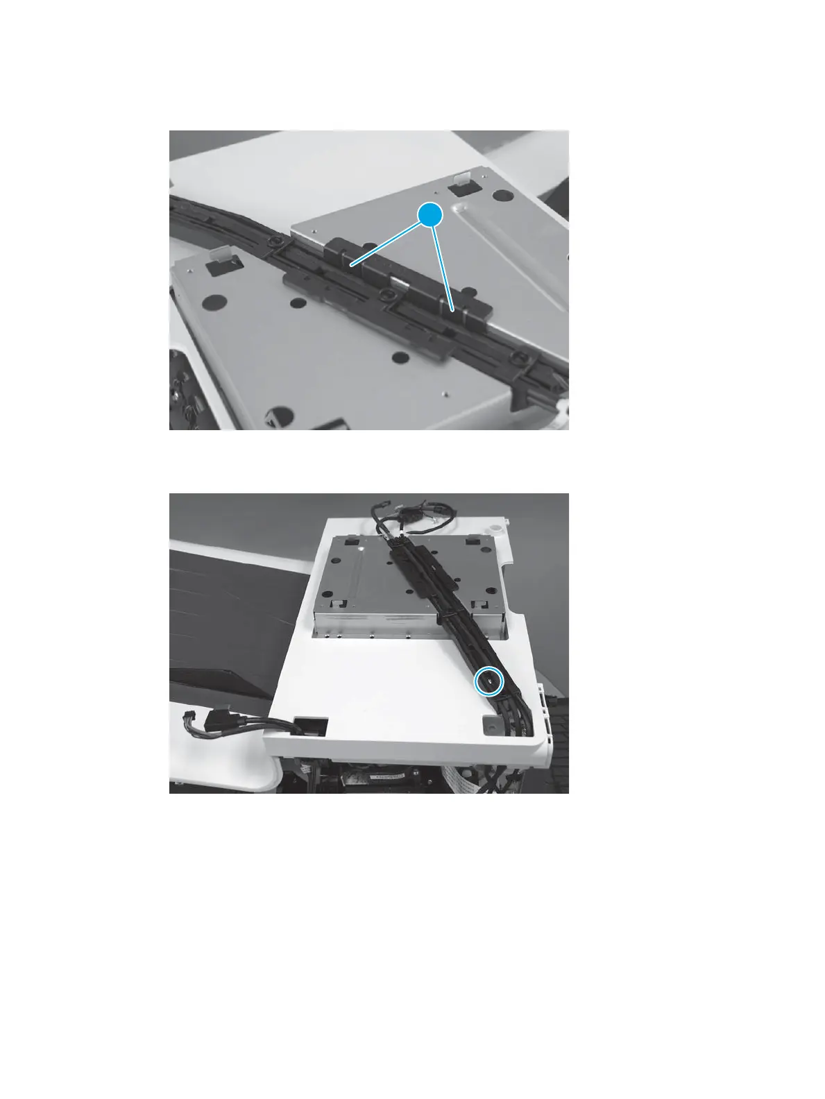
6.
Install the guide
, and mak
e sure tha
t the two tabs (cal
lout 1) snap int
o place.
Figure 1-363
Instal
l the guide
1
7.
Install the guide
, and then install one scr
ew.
Figure 1-364
Instal
l one screw
ENWW
Remov
al and replac
ement proc
edures
243
280
282
Table of Contents
Main Page
Removal and replacement
39
For additional service and support
40
Removal and replacement strategy
41
Introduction
41
Considerations during removal and replacement
41
Electrostatic discharge
42
Required tools
42
Fasteners types
42
Service approach
42
Before performing service
42
After performing service
43
Post-service test
43
Print-quality test
43
Copy-quality test (M586)
43
Fax-quality test (M586f models)
44
Parts removal order
44
Removal and replacement procedures
45
Customer self-repair (CSR) A parts and assemblies
45
Removal and replacement: Ink cartridges
46
Introduction
46
Before performing service
46
Required tools
46
After performing service
47
Post service test
47
Step 1: Remove the ink cartridges
47
Step 2: Unpack the replacement assembly
48
Step 3: Install the ink cartridges
49
Removal and replacement: Output bin
51
Introduction
51
Before performing service
51
Required tools
51
After performing service
51
Post service test
51
Step 1: Remove the right cover (outer)
51
Step 2: Remove the output bin
52
Step 2: Unpack the replacement assembly
53
Step 4: Install the output bin
54
Step 5: Install the right cover (outer)
55
Removal and replacement: Document feeder retention clips (586)
57
Introduction
57
Before performing service
57
Required tools
57
After performing service
57
Post service test
57
Step 1: Remove the retention clips
57
Step 2: Unpack the replacement assembly
60
Step 3: Install the retention clips
61
Removal and replacement: Document feeder white backing (586)
65
Introduction
65
Before performing service
65
Required tools
65
After performing service
65
Post service test
65
Step 1: Remove the white backing
65
Step 2: Unpack the replacement assembly
68
Step 3: Install the white backing
69
Removal and replacement: Control panel (586)
72
Introduction
72
Before performing service
72
Required tools
72
After performing service
72
Post service test
72
Step 1: Remove the control panel (586)
72
Step 2: Unpack the replacement assembly
76
Step 3: Install the control panel (556)
77
Removal and replacement: Control panel keyboard (586z)
83
Introduction
83
Before performing service
83
Required tools
83
After performing service
83
Post service test
83
Step 1: Remove the control panel keyboard
83
Step 2: Unpack the replacement assembly
87
Step 3: Install the control panel keyboard
88
Removal and replacement: embedded MultiMedia Card (eMMC) (556dn)
92
Introduction
92
Before performing service
92
Required tools
92
After performing service
92
Post service test
93
Step 1: Remove the formatter cover
93
Step 2: Remove the embedded MultiMedia Card (eMMC)
93
Step 3: Unpack the replacement assembly
94
Step 4: Install the eMMC
95
Step 5: Install the formatter cover
96
Step 6: Reinstall the product firmware
96
Removal and replacement: Hard-disk drive (HDD)
98
Introduction
98
Before performing service
98
Required tools
98
After performing service
98
Post service test
99
Step 1: Remove the formatter cover
99
Step 2: Remove the hard-disk drive (HDD)
99
Step 3: Unpack the replacement assembly
100
Step 5: Install the HDD
101
Step 6: Install the formatter cover
103
Step 7: Reinstall the product firmware
103
Customer self-repair (CSR) B parts and assemblies
105
Removal and replacement: Control panel (556)
106
Introduction
106
Before performing service
106
Required tools
106
After performing service
106
Post service test
106
Step 1: Removal the control panel (556)
107
Step 2: Unpack the replacement assembly
109
Step 3: Install the control panel (556)
110
Field replaceable units (FRUs) / Bench repairable units (BRUs)
114
Removal and replacement: External panels, covers, and doors
114
Removal and replacement: Left door
115
Introduction
115
Before performing service
115
Required tools
115
After performing service
115
Post service test
115
Step 1: Remove the left door
115
Step 2: Unpack the replacement assembly
118
Step 1: Install the left door
119
Removal and replacement: Scanner control board (SCB) cover
122
Introduction
122
Before performing service
122
Required tools
122
After performing service
122
Post service test
122
Step 1: Remove the scanner control board (SCB) cover
122
Step 2: Unpack the replacement assembly
123
Step 3: Install the SCB cover
124
Removal and replacement: Formatter cover
127
Introduction
127
Before performing service
127
Required tools
127
After performing service
127
Post service test
127
Step 1: Remove the formatter cover
127
Step 2: Unpack the replacement assembly
128
Step 3: Install the formatter cover
129
Removal and replacement: Right cover (outer)
130
Introduction
130
Before performing service
130
Required tools
130
After performing service
130
Post service test
130
Step 1: Remove the right cover (outer)
130
Step 2: Unpack the replacement assembly
131
Step 3: Install the right cover (outer)
132
Removal and replacement: Left-rear top cover cap (556)
134
Introduction
134
Before performing service
134
Required tools
134
After performing service
134
Post service test
134
Step 1: Remove the left-rear top cover cap (556)
134
Step 2: Unpack the replacement assembly
135
Step 3: Install the left-rear top cover cap (556)
136
Removal and replacement: Left-front top cover cap (556)
137
Introduction
137
Before performing service
137
Required tools
137
After performing service
137
Post service test
137
Step 1: Remove the left-front top cover cap (556)
137
Step 2: Unpack the replacement assembly
138
Step 3: Install the left-front top cover cap (556)
139
Removal and replacement: Left rear cover
140
Introduction
140
Before performing service
140
Required tools
140
After performing service
140
Post service test
140
Step 1: Remove the left-rear top cover cap (556)
140
Step 2: Remove the left rear cover
141
Step 3: Unpack the replacement assembly
142
Step 4: Install the left rear cover
143
Step 5: Install the left-rear top cover cap (556)
145
Removal and replacement: Left front cover
146
Introduction
146
Before performing service
146
Required tools
146
After performing service
146
Post service test
146
Step 1: Remove the left-front top cover cap (556)
146
Step 2: Remove the left front cover
147
Step 3: Unpack the replacement assembly
148
Step 4: Install the left front cover
149
Step 5: Install the left-front top cover cap (556)
151
Removal and replacement: Rear cover
152
Introduction
152
Before performing service
152
Required tools
152
After performing service
152
Post service test
152
Step 1: Remove the right cover (outer)
152
Step 2: Remove the formatter cover
153
Step 3: Remove the rear cover
154
Step 4: Unpack the replacement assembly
156
Step 5: Install the rear cover
157
Step 6: Install the formatter cover
159
Step 7: Install the right cover (outer)
160
Removal and replacement: Top cover (556)
162
Introduction
162
Before performing service
162
Required tools
163
After performing service
163
Post service test
163
Step 1: Removal the control panel (556)
163
Step 2: Remove the left-rear top cover cap (556)
166
Step 3: Remove the left rear cover
166
Step 4: Remove the left-front top cover cap (556)
168
Step 5: Remove the left front cover
168
Step 6: Remove the right cover (outer)
170
Step 7: Remove the formatter cover
171
Step 8: Remove the rear cover
171
Step 9: Remove the top cover (556)
173
Step 10: Install the top cover (556)
176
Step 11: Install the rear cover
179
Step 12: Install the formatter cover
182
Step 13: Install the right cover (outer)
182
Step 14: Install the left front cover
183
Step 15: Install the left-front top cover cap (556)
185
Step 16: Install the left rear cover
185
Step 17: Install the left-rear top cover cap (556)
187
Step 18: Install the control panel (556)
187
Removal and replacement: Top cover (586)
191
Introduction
191
Before performing service
191
Required tools
191
After performing service
192
Post service test
192
Step 1: Remove the integrated scanner assembly (ISA; 586)
192
Step 2: Remove the left rear cover
203
Step 3: Remove the left front cover
205
Step 4: Remove the right cover (outer)
206
Step 5: Remove the formatter cover
207
Step 6: Remove the rear cover
208
Step 7: Remove the top cover (586)
210
Step 8: Unpack the replacement assembly
215
Step 9: Install the top cover (586)
216
Step 10: Install the rear cover
221
Step 11: Install the formatter cover
224
Step 12: Install the right cover (outer)
224
Step 13: Install the left front cover
225
Step 14: Install the left rear cover
227
Step 15: Install the integrated scanner assembly (ISA; 586)
228
Removal and replacement: Front cover
242
Introduction
242
Before performing service
243
Required tools
243
After performing service
243
Post service test
243
Step 1: Removal the control panel (556)
243
Step 2: Remove the integrated scanner assembly (ISA) (586)
246
Step 3: Remove the left-rear top cover cap (556)
258
Step 4: Remove the left rear cover
259
Step 5: Remove the left-front top cover cap (556)
260
Step 6: Remove the left front cover
261
Step 7: Remove the right cover (outer)
262
Step 8: Remove the formatter cover
263
Step 9: Remove the rear cover
263
Step 10: Remove the top cover (556)
265
Step 11: Remove the top cover (586)
268
Step 12: Removal the front cover
273
Step 13: Unpack the replacement assembly
275
Step 14: Install the front cover
276
Step 15: Install the top cover (586)
278
Step 16: Install the top cover (556)
283
Step 17: Install the rear cover
286
Step 18: Install the formatter cover
289
Step 19: Install the right cover (outer)
289
Step 20: Install the left front cover
290
Step 21: Install the left-front top cover cap (556)
292
Step 22: Install the left rear cover
293
Step 23: Install the left-rear top cover cap (556)
294
Step 24: Install the integrated scanner assembly (ISA) (586)
294
Step 25: Install the control panel (556)
307
Removal and replacement: Output-bin inner cover
310
Introduction
310
Before performing service
311
Required tools
311
After performing service
311
Post service test
311
Step 1: Removal the control panel (556)
311
Step 2: Remove the integrated scanner assembly (ISA; 586)
314
Step 3: Remove the left-rear top cover cap (556)
326
Step 4: Remove the left rear cover
327
Step 5: Remove the left-front top cover cap (556)
328
Step 6: Remove the left front cover
329
Step 7: Remove the right cover (outer)
330
Step 8: Remove the formatter cover
331
Step 9: Remove the rear cover
331
Step 10: Remove the top cover (556)
333
Step 11: Remove the top cover (586)
336
Step 12: Removal the front cover
341
Step 13: Remove the output-bin inner cover
343
Step 14: Install the output-bin inner cover
344
Step 15: Install the front cover
346
Step 16: Install the top cover (586)
348
Step 17: Install the top cover (556)
353
Step 18: Install the rear cover
356
Step 20: Install the formatter cover
359
Step 20: Install the right cover (outer)
359
Step 21: Install the left front cover
360
Step 22: Install the left-front top cover cap (556)
362
Step 23: Install the left rear cover
363
Step 24: Install the left-rear top cover cap (556)
364
Step 25: Install the integrated scanner assembly (ISA; 586)
364
Step 26: Install the control panel (556)
377
Removal and replacement: Internal parts and assemblies
380
Removal and replacement: Tray 2-X rollers
381
Introduction
381
Before performing service
381
Required tools
381
After performing service
382
Post service test
382
Step 1: Remove the tray
382
Step 2: Remove the separation and pick roller assemblies
383
Step 3: Unpack the replacement assembly
387
Step 4: Install the pickup and separation roller assemblies
388
Step 5: Install the tray
391
Removal and replacement: Formatter
392
Introduction
392
Before performing service
392
Required tools
393
After performing service
393
Post service test
393
Step 1: Remove the formatter cover
393
Step 2: Remove the fax PCA
394
Step 3: Remove the hard-disk drive (HDD)
395
Step 4: Remove the embedded MultiMedia Card (eMMC)
396
Step 5: Remove the small outline dual in-line memory module (SODIMM)
396
Step 6: Remove the formatter
398
Step 7: Unpack the replacement assembly
400
Step 8: Install the formatter
401
Step 9: Install the small outline dual in-line memory module (SODIMM)
403
Step 10: Install the embedded MultiMedia Card (eMMC)
404
Step 11: Install the hard-disk drive (HDD)
405
Step 12: Install the fax PCA
407
Step 13: Install the formatter cover
408
Removal and replacement: Document feeder assembly (586)
410
Introduction
410
Before performing service
410
Required tools
410
After performing service
410
Post service test
410
Step 1: Remove the scanner controlle board (SCB) cover
411
Step 2: Remove the document feeder assembly (M586)
411
Step 3: Unpack the replacement assembly
414
Step 4: Install the document feeder assembly (M586)
415
Step 5: Install the SCB cover
416
Step 6: Install the white backing
418
Step 7: Reset the firmware counter
420
Removal and replacement: Scanner control board (SCB) (586)
421
Introduction
421
Before performing service
421
Required tools
421
After performing service
422
Post service test
422
Step 1: Remove the scanner control board (SCB) cover
422
Step 2: Remove the right cover (outer)
423
Step 3: Remove the formatter cover
424
Step 4: Remove the rear cover
424
Step 5: Remove the scanner control board (SCB) (M586)
426
Step 6: Unpack the replacement assembly
430
Step 7: Install the SCB (M586)
431
Step 8: Install the rear cover
434
Step 9: Install the right cover (outer)
437
Step 10: Install the formatter cover
438
Step 11: Install the SCB cover
438
Removal and replacement: Sub-scanner assembly (SSA) (586)
441
Introduction
441
Before performing service
441
Required tools
442
After performing service
442
Post service test
442
Step 1: Remove the white backing
442
Step 2: Removal the control panel (586)
443
Step 3: Remove the scanner control board (SCB) cover
448
Step 4: Remove the right cover (outer)
449
Step 5: Remove the formatter cover
450
Step 6: Remove the rear cover
450
Step 7: Remove the scanner control board (SCB) (M586)
452
Step 8: Remove the document feeder assembly (M586)
456
Step 9: Remove the sub-scanner assembly (SSA)
458
Step 10: Unpack the replacement assembly
463
Step 11: Install the sub-scanner assembly (SSA)
464
Step 12: Install the document feeder assembly (M586)
470
Step 13: Install the SCB (M586)
471
Step 14: Install the rear cover
475
Step 15: Install the formatter cover
477
Step 16: Install the right cover (outer)
478
Step 17: Install the SCB cover
479
Step 18: Install the control panel (556)
480
Step 19: Install the white backing
485
Removal and replacement: Power supply
486
Introduction
486
Before performing service
486
Required tools
486
After performing service
487
Post service test
487
Step 1: Remove the right cover (outer)
487
Step 2: Remove the formatter cover
488
Step 3: Remove the rear cover
488
Step 4: Remove the formatter and formatter cage (586)
490
Step 5: Remove the formatter and formatter cage (556)
493
Step 6: Remove the power supply
496
Step 7: Unpack the replacement assembly
497
Step 8: Install the power supply
498
Step 9: Install the formatter and formatter cage (556)
500
Step 10: Install the formatter and formatter cage (586)
502
Step 11: Install the rear cover
505
Step 12: Install the formatter cover
507
Step 13: Install the right cover (outer)
508
Print mechanism kit (556)
510
Introduction
510
Before performing service
511
Required tools
511
After performing service
511
Post service test
511
Acclimation
511
Cold temperatures can affect the print mechanism
511
Acclimation process
512
Ink cartridge acclimation
512
Installation notes
512
Keep the packaging
512
Necessary tools and the PM process
512
Removal and replacement strategy
514
Tracking fasteners used in this printer
514
Step 1: Unpack the Replacement Print Mechanism (PM)
514
Step 2: Remove the right cover (outer) (PM)
517
Step 3: Remove the formatter cover (PM)
518
Step 4: Remove the rear cover (PM)
519
Step 5: Turn the power off defective unit (DU)
521
Step 6: Remove the formatter cover (DU)
522
Step 7: Remove the right cover (outer) (DU)
522
Step 8: Remove the rear cover (DU)
523
Step 9: Remove the formatter and formatter cage (DU)
525
Step 10: Remove the power supply (DU)
528
Step 11: Remove the power supply mounting bracket (DU)
529
Step 12: Remove the blank cover (DU)
530
Step 13: Removal the control panel (DU)
532
Step 14: Install the control panel (PM)
535
Step 15: Install the blank cover (PM)
538
Step 16: Install the power supply mounting bracket (PM)
540
Step 17: Install the power supply (PM)
541
Step 18: Install the formatter and formatter cage (PM)
543
Step 19: Install the rear cover (PM)
545
Step 20: Install the right cover (outer) (PM)
548
Step 21: Install the formatter cover (PM)
549
Step 22: Turn the power on print mechanism (PM)
549
Step 23: Prepare the Defective Unit (DU) for Shipping
550
Print mechanism kit (586)
552
Introduction
552
Before performing service
553
Required tools
553
After performing service
553
Post service test
553
Acclimation
553
Cold temperatures can affect the print mechanism
553
Acclimation process
554
Ink cartridge acclimation
554
Installation notes
554
Keep the packaging
554
Necessary tools and the PM process
554
Removal and replacement strategy
556
Tracking fasteners used in this printer
556
Step 1: Unpack the Replacement Print Mechanism (PM)
557
Step 2: Remove the right cover (outer) (PM)
559
Step 3: Remove the formatter cover (PM)
560
Step 4: Remove the rear cover (PM)
561
Step 5: Turn the power off defective unit (DU)
563
Step 6: Remove the formatter cover (DU)
564
Step 7: Remove the right cover (outer) (DU)
564
Step 8: Remove the rear cover (DU)
565
Step 9: Remove the formatter and formatter cage (DU)
567
Step 10: Remove the power supply (DU)
570
Step 11: Remove the power supply mounting bracket (DU)
571
Step 12: Remove the blank cover (DU)
572
Step 13: Remove the Integrated Scanner Assembly (ISA) (DU)
574
Step 14: Install the Integrated Scanner Assembly (ISA) (PM)
586
Step 15: Install the blank cover (PM)
598
Step 16: Install the power supply mounting bracket (PM)
600
Step 17: Install the power supply (PM)
601
Step 18: Install the formatter and formatter cage (PM)
603
Step 19: Install the rear cover (PM)
606
Step 20: Install the right cover (outer) (PM)
608
Step 21: Install the formatter cover (PM)
609
Step 22: Turn the power on print mechanism (PM)
610
Step 23: Prepare the Defective Unit (DU) for Shipping
610
Removal and replacement: Trays
612
Removal and replacement: Tray 2
613
Introduction
613
Before performing service
613
Required tools
613
After performing service
613
Post service test
613
Step 1: Remove the tray
613
Step 2: Unpack the replacement assembly
614
Step 3: Install the tray
615
Removal and replacement: Tray 3-X
616
Introduction
616
Before performing service
616
Required tools
616
After performing service
616
Post service test
616
Step 1: Remove the tray
616
Step 2: Unpack the replacement assembly
617
Step 3: Install the tray
618
Removal and replacement: Accessories
619
Install accessory: Document feeder rollers (586)
620
Introduction
620
Before performing service
620
Required tools
620
After performing service
620
Post service test
621
Step 1: Remove the document feeder pickup and feed roller assembly
621
Step 2: Remove the document feeder separation roller assembly
622
Step 3: Unpack the replacement assembly
623
Step 4: Install the document feeder separation roller assembly
624
Step 5: Install the document feeder pickup and feed roller assembly
626
Step 6: Reset the firmware counter
628
Install accessory: Fax printed-circuit board
629
Introduction
629
Before performing service
629
Required tools
629
After performing service
629
Post service test
630
Step 1: Remove the formatter cover
630
Step 2: Remove the fax printed-circuit board (PCA)
630
Step 3: Unpack the replacement assembly
631
Step 4: Install the fax PCA
632
Step 5: Install the formatter cover
633
Install accessory: Small outline dual in-line memory module (SODIMM)
635
Introduction
635
Before performing service
635
Required tools
635
After performing service
635
Post service test
635
Step 1: Remove the formatter cover
636
Step 2: Remove the small outline dual in-line memory module (SODIMM)
636
Step 3: Unpack the replacement assembly
638
Step 4: Install the SODIMM
639
Step 5: Install the formatter cover
640
Install accessory: HP Foreign interface harness (FIH) solution
642
Introduction
642
Before performing service
642
Required tools
642
After performing service
642
Post service test
642
Step 1: Unpack the Foreign Interface Harness (FIH) accessory
642
Step 2: Install the FIH accessory
642
Install accessory: Internal USB ports
644
Introduction
644
Before performing service
644
Required tools
644
After performing service
644
Post service test
644
Step 1: Remove the formatter cover
645
Step 2: Unpack the replacement assembly
645
Step 3: Install the internal USB port module
646
Step 4: Install the formatter cover
648
Parts and diagrams
649
For additional service and support
650
Assembly locations
651
Printer front view (556 models)
651
Printer back view (556 models)
652
Printer front view (586 models)
653
Printer back view (586 models)
654
Order parts, accessories, and supplies
655
Ordering
655
Orderable parts
655
Supplies and accessories
655
Customer self-repair parts
657
Related documentation and software
658
Parts and diagrams: Document feeder and scanner whole units (586)
660
Exploded view and parts list
660
Parts and diagrams: Covers
662
Exploded view and parts list (556 covers)
662
Exploded view and parts list (586 covers)
664
Parts and diagrams: Internal assemblies
666
Exploded view and parts list
666
Alphabetical parts list
668
Numerical parts list
672
Index
677
Other manuals for HP PageWide Enterprise Color 556
Troubleshooting Manual
12 pages
Related product manuals
HP PageWide Managed Color E77650
264 pages
PageWide Managed Color Flow MFP E77650
40 pages
Color LaserJet Enterprise M750
134 pages
Color LaserJet Enterprise CP4525
2 pages
Color LaserJet Enterprise CM4540
386 pages
Color LaserJet Enterprise CP5520
166 pages
Color LaserJet Enterprise flow M880z
202 pages
Color LaserJet Enterprise M680 series
28 pages
LASERJET ENTERPRISE 500 COLOR MFP M575
13 pages
LASERJET ENTERPRISE 700 COLOR MFP M775dn
352 pages
Color LaserJet Enterprise MFP M680 series
568 pages
Color LaserJet Enterprise CM4540 MFP Series
386 pages
 Loading...