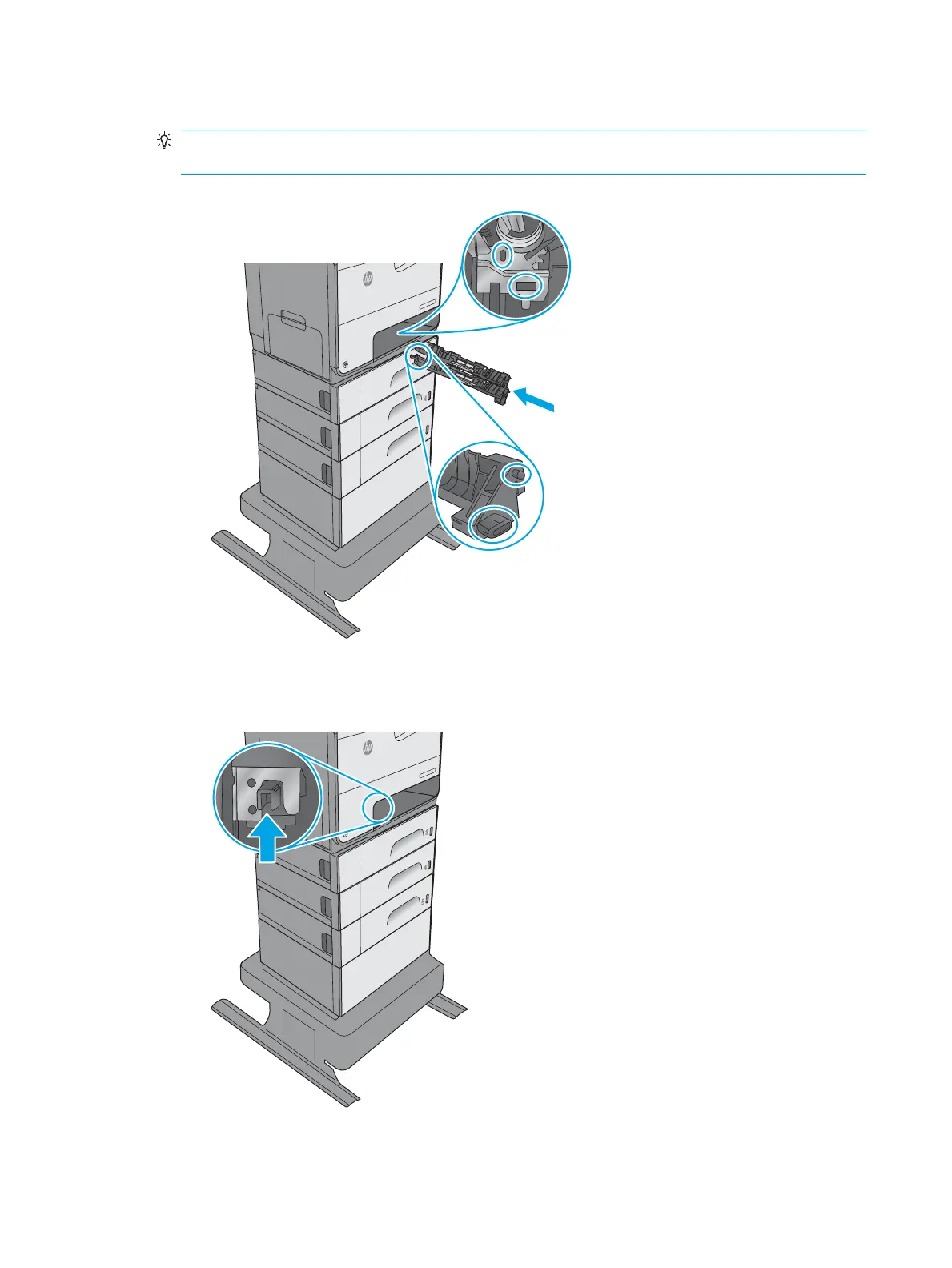
4. Install the back end of the separation roller assembly into the printer.
Reinstallation tip: There is a pin and a tab on the assembly that correspond to a hole and a slot in the
sheet-metal rear wall of the tray cavity.
Figure 1-572 Install the back end of the assembly
Off
i
c
e
j
e
t
E
nt
e
rpri
s
e
Colo
r
X55
6
5. Push up on the front end of the separation roller assembly to install it in the holder.
Figure 1-573 Install the front end of the assembly
Off
i
c
e
j
e
t
E
nt
e
rpri
s
e
Colo
r
X55
6
352 Chapter 1 Removal and replacement ENWW
 Loading...