Inter-integrated circuit (I2C) interface RM0453
1050/1450 RM0453 Rev 5
• Wake-up from Stop mode on address match
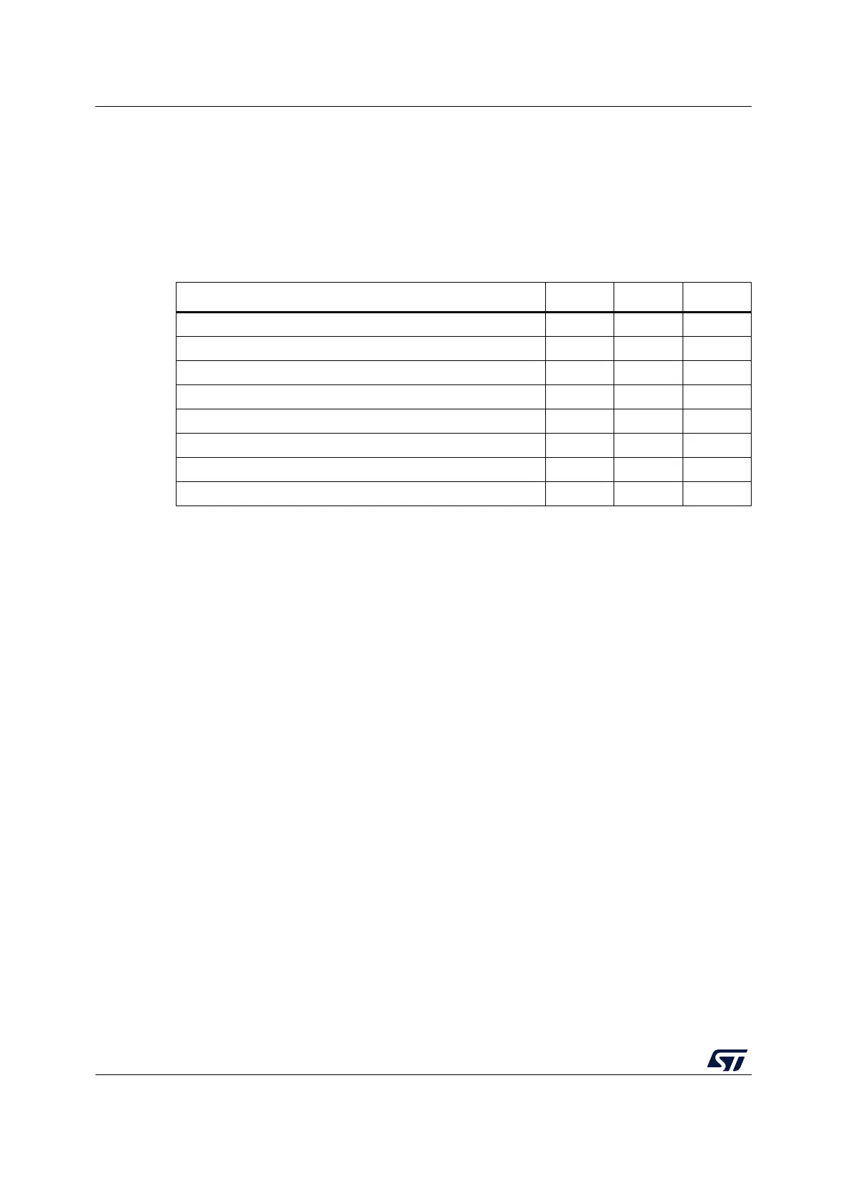
34.3 I2C implementation
The devices incorporate up to three I²C-bus controllers, I2C1, I2C2, and I2C3, with full or
limited feature sets as shown in the following table.
34.4 I2C functional description
In addition to receiving and transmitting data, this interface converts them from serial to
parallel format and vice versa. The interrupts are enabled or disabled by software. The
interface is connected to the I
2
C bus by a data pin (SDA) and by a clock pin (SCL). It can be
connected with a standard (up to 100 kHz), Fast-mode (up to 400 kHz) or Fast-mode Plus
(up to 1 MHz) I
2
C bus.
This interface can also be connected to an SMBus with data (SDA) and clock (SCL) pins.
If the SMBus feature is supported, the optional SMBus Alert pin (SMBA) is also available.
Table 222. STM32WL5x I2C implementation
I2C features
(1)
1. X = supported.
I2C1
(2)
2. The register content is lost in Stop 2 mode.
I2C2
(2)
I2C3
7-bit addressing mode X X X
10-bit addressing mode X X X
Standard-mode (up to 100 kbit/s) X X X
Fast-mode (up to 400 kbit/s) X X X
Fast-mode Plus with 20 mA output drive I/Os (up to 1 Mbit/s) X X X
Independent clock X X X
Wake-up from Stop mode X
(3)
3. Wake-up supported from Stop 0 and Stop 1 modes.
X
(3)
X
(4)
4. Wake-up supported from Stop 0, Stop 1 and Stop 2 modes.
SMBus/PMBus X X X