RM0453 Rev 5 1033/1450
RM0453 Tamper and backup registers (TAMP)
1048
33.3 TAMP functional description
33.3.1 TAMP block diagram
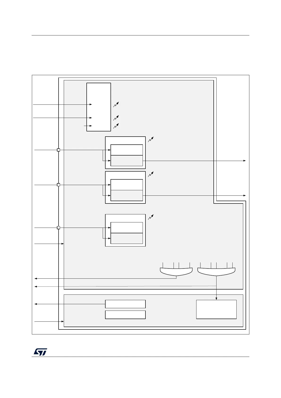
Figure 275. TAMP block diagram
1. The number of external and internal tampers depends on products.
MSv50968V2
TAMP_IN1
tamp_pclk clock domain
Registers interface
tamp_pclk
IRQ interface
TAMP1F
Tamper detection
EDGE detection
LEVEL detection
TAMP2F
Tamper detection
EDGE detection
LEVEL detection
...
TAMPxF
(1)
Tamper detection
EDGE detection
LEVEL detection
...
Backup registers
tamp_it
tamp_erase
tamp_ker_ck
tamp_ker_ck clock domain
TAMP_IN2
TAMP_INx
tamp_trg1
tamp_trg2
Internal
tamper
detection
tamp_itamp1 ITAMP1F
...
tamp_itampy
Monotonic
counter
overflow
ITAMP1
...
ITAMPy
(1)
ITAMP8
ITAMPyF
ITAMP8F
...
TAMP1F when TAMP1NOER=0
TAMPxF when TAMPxNOER=0
...
ITAMP1F when ITAMP1NOER=0
ITAMPyF when ITAMPyNOER=0
BKERASE
...
TAMP1F
TAMPxF
...
ITAMP1F
ITAMPyF
tamp_evt