Cyclic redundancy check calculation unit (CRC) RM0453
526/1450 RM0453 Rev 5
17.3 CRC functional description
17.3.1 CRC block diagram
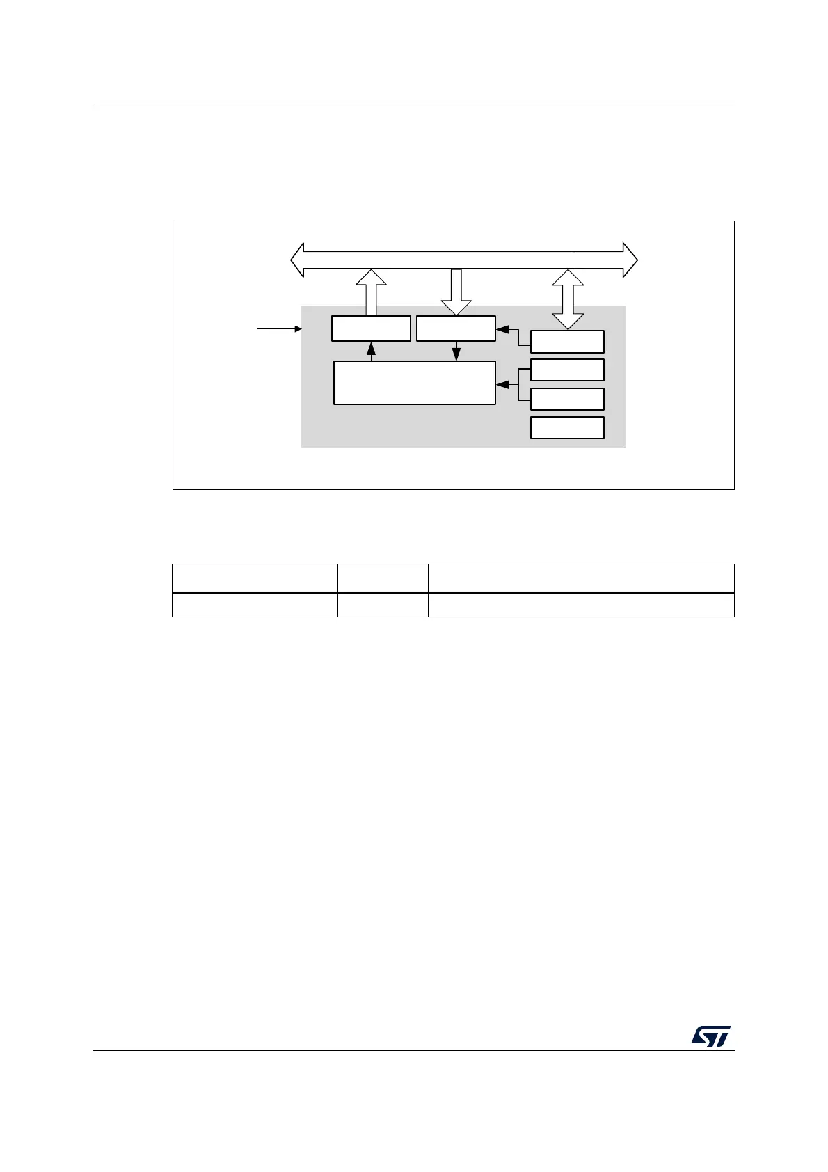
Figure 57. CRC calculation unit block diagram
17.3.2 CRC internal signals
17.3.3 CRC operation
The CRC calculation unit has a single 32-bit read/write data register (CRC_DR). It is used to
input new data (write access), and holds the result of the previous CRC calculation (read
access).
Each write operation to the data register creates a combination of the previous CRC value
(stored in CRC_DR) and the new one. CRC computation is done on the whole 32-bit data
word or byte by byte depending on the format of the data being written.
The CRC_DR register can be accessed by word, right-aligned half-word and right-aligned
byte. For the other registers only 32-bit accesses are allowed.
The duration of the computation depends on data width:
• 4 AHB clock cycles for 32 bits
• 2 AHB clock cycles for 16 bits
• 1 AHB clock cycles for 8 bits
An input buffer allows a second data to be immediately written without waiting for any wait
states due to the previous CRC calculation.
MS19882V3
Data register
(output)
read access
Data register
(input)
write access
32-bit AHB bus
crc_hclk
CRC computation
32-bit accesses
CRC_INIT
CRC_CR
CRC_POL
CRC_IDR
Table 98. CRC internal input/output signals
Signal name Signal type Description
crc_hclk Digital input AHB clock