Advanced-control timer (TIM1) RM0453
744/1450 RM0453 Rev 5
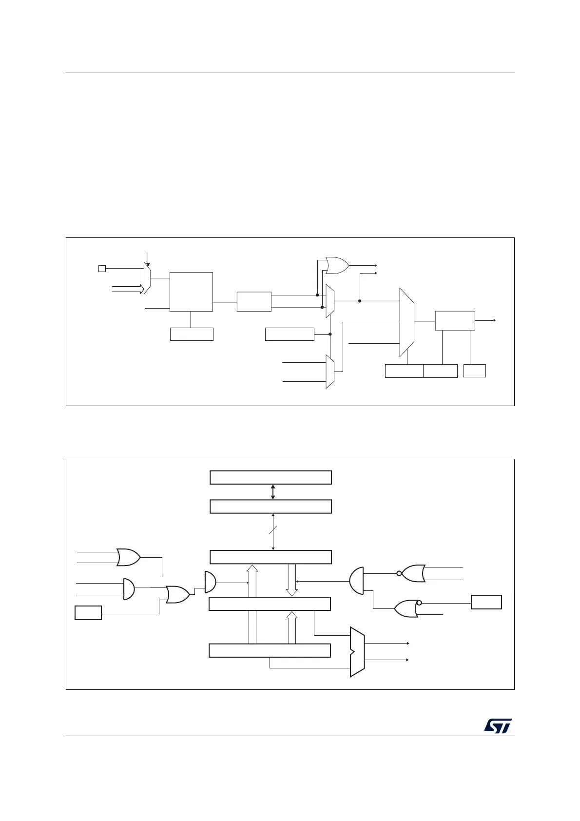
25.3.6 Capture/compare channels
Each Capture/Compare channel is built around a capture/compare register (including a
shadow register), an input stage for capture (with digital filter, multiplexing, and prescaler,
except for channels 5 and 6) and an output stage (with comparator and output control).
Figure 156 to Figure 159 give an overview of one Capture/Compare channel.
The input stage samples the corresponding TIx input to generate a filtered signal TIxF.
Then, an edge detector with polarity selection generates a signal (TIxFPx) which can be
used as trigger input by the slave mode controller or as the capture command. It is
prescaled before the capture register (ICxPS).
Figure 156. Capture/compare channel (example: channel 1 input stage)
The output stage generates an intermediate waveform which is then used for reference:
OCxRef (active high). The polarity acts at the end of the chain.
Figure 157. Capture/compare channel 1 main circuit
MSv40120V2
0
1
ICPS[1:0]
TI1F_ED
To the slave mode controller
TI1FP1
11
01
CC1S[1:0]
IC1
TI2FP1
TRC
(from slave mode
controller)
10
IC1PS
0
1
TIMx_CCER
CC1P/CC1NP
TIMx_CCMR1
Edge
detector
TI1F_Rising
TI1F_Falling
Filter
downcounter
ICF[3:0]
Divider
/1, /2, /4, /8
TIMx_CCMR1
TIMx_CCER
TI2F_Rising
(from channel 2)
TI2F_Falling
(from channel 2)
TI1F
f
DTS
CC1E
TIMx_CH1
TI1[1..15]
TI1[0]
TIMx_TISEL[3:0]
MSv63030V1
CC1E
compare shadow register
Comparator
Capture/compare preload register
Counter
IC1PS
CC1S[0]
CC1S[1]
Capture
Input mode
CC1S[0]
CC1S[1]
Output mode
UEV
OC1PE
(from time
base unit)
Compare
transfer
APB Bus
16/32-bit
MCU-peripheral interface
TIMx_CCMR1
OC1PE
CNT>CCR1
CNT=CCR1
TIMx_EGR
CC1G