Inter-integrated circuit (I2C) interface RM0453
1052/1450 RM0453 Rev 5
34.4.2 I2C pins and internal signals
34.4.3 I2C clock requirements
The I2C kernel is clocked by I2CCLK.
The I2CCLK period t
I2CCLK
must respect the following conditions:
• t
I2CCLK
< (t
LOW
- t
filters
) / 4
• t
I2CCLK
< t
HIGH
with:
t
LOW
: SCL low time and t
HIGH
: SCL high time
t
filters
:
when enabled, sum of the delays brought by the analog and by the digital filters.
The digital filter delay is DNF x t
I2CCLK
.
The PCLK clock period t
PCLK
must respect the condition:
• t
PCLK
< 4 / 3 t
SCL
(t
SCL
: SCL period)
Caution: When the I2C kernel is clocked by PCLK, this clock must respect the conditions for t
I2CCLK
.
34.4.4 Mode selection
The interface can operate in one of the four following modes:
• Slave transmitter
• Slave receiver
• Master transmitter
• Master receiver
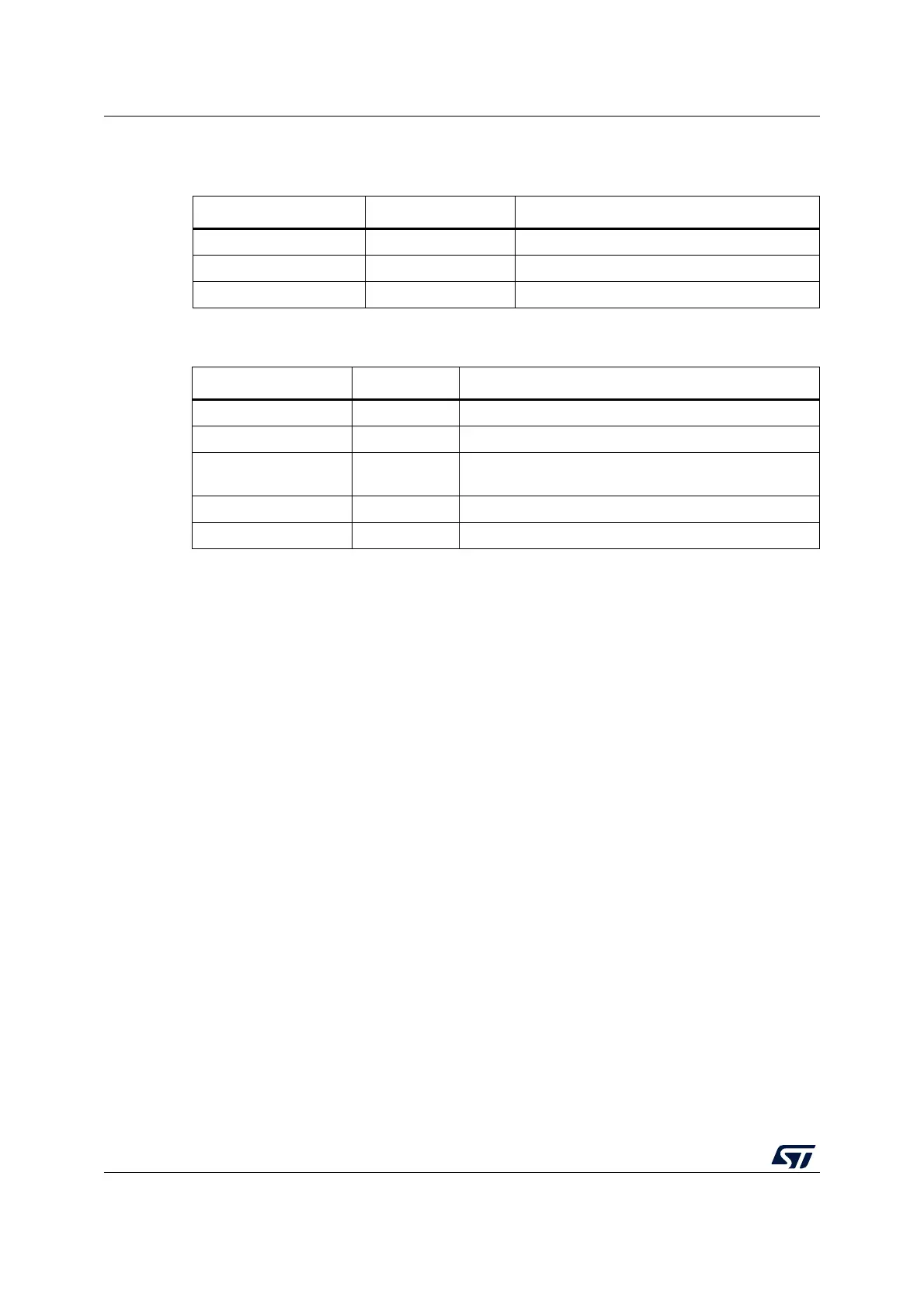
Table 223. I2C input/output pins
Pin name Signal type Description
I2C_SDA Bidirectional I2C data
I2C_SCL Bidirectional I2C clock
I2C_SMBA Bidirectional SMBus alert
Table 224. I2C internal input/output signals
Internal signal name Signal type Description
i2c_ker_ck Input I2C kernel clock, also named I2CCLK in this document
i2c_pclk Input I2C APB clock
i2c_it Output
I2C interrupts, refer to Table 237 for the full list of
interrupt sources
i2c_rx_dma Output I2C receive data DMA request (I2C_RX)
i2c_tx_dma Output I2C transmit data DMA request (I2C_TX)