RM0453 Rev 5 373/1450
RM0453 Hardware semaphore (HSEM)
385
8.3 Functional description
8.3.1 HSEM block diagram
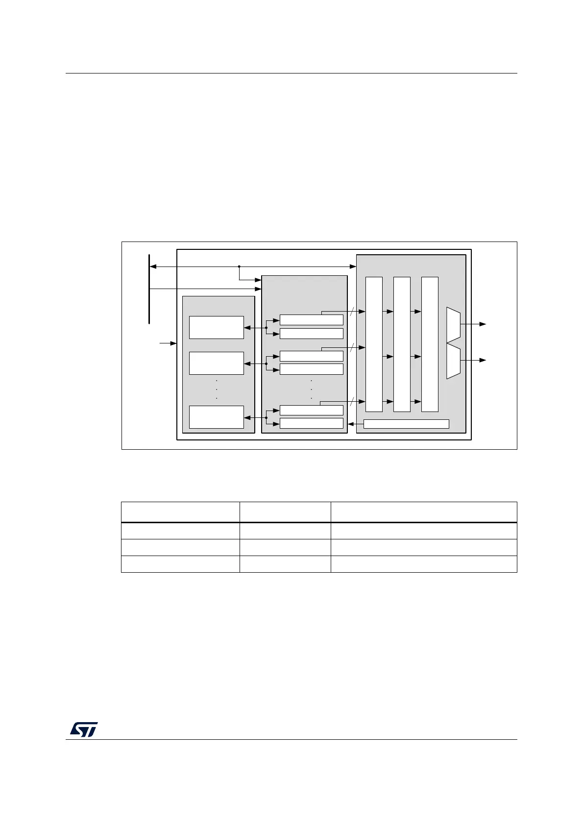
As shown in Figure 33, the HSEM is based on three sub-blocks:
• the semaphore block containing the semaphore status and IDs
• the semaphore interface block providing AHB access to the semaphore via the
HSEM_Rx and HSEM_RLRx registers
• the interrupt interface block providing control for the interrupts via HSEM_CnISR,
HSEM_CnIER, HSEM_CnMISR, and HSEM_CnICR registers.
Figure 33. HSEM block diagram
8.3.2 HSEM internal signals
8.3.3 HSEM lock procedures
There are two lock procedures, namely 2-step (write) lock and 1-step (read) lock. The two
procedures can be used concurrently.
MS40530V5
HSEM
Interrupt interface
HSEM_CnMISR[1:0]
HSEM_CnICR[1:0]
Semaphore interface
Sem_Ints
32-bit AHB bus
HSEM_RLR0
HSEM_RLR1
HSEM_RLRx
Sem_Ints
Sem_Ints
Semaphore block
Semaphore 0
Semaphore 1
Semaphore x
2
2
2
Bus master ID
HSEM_CnIER[1:0]
HSEM_CnISR[1:0]
HSEM_R0
HSEM_R1
HSEM_Rx
hsem_int1_it
hsem_int2_it
hclk
Table 64. HSEM internal input/output signals
Signal name Signal type Description
AHB bus Digital input/output AHB register access bus
BusMasterID Digital input AHB bus master ID
hsem_intn_it Digital output Interrupt n line (n = 1 to 2)