Reset and clock control (RCC) RM0453
302/1450 RM0453 Rev 5
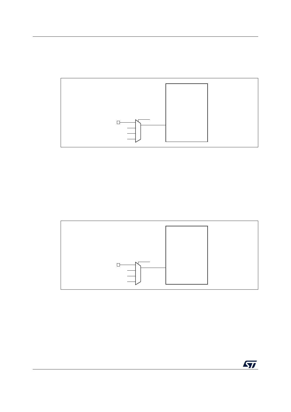
7.2.20 Internal/external clock measurement with TIM16/TIM17
The frequency of all on-board clock sources can be indirectly measured by mean of the
TIM16 or TIM17 channel 1 input capture, as shown in Figure 31 and Figure 32.
Figure 31. Frequency measurement with TIM16 in capture mode
The TIM16 input capture channel can be a GPIO line or an internal clock of the MCU. This
selection is performed through the TI1_RMP[1:0] bits in the TIM16_OR register. The
possibilities are listed below:
• TIM16 channel1 is connected to the GPIO (refer to the alternate function mapping in
the device datasheets).
• TIM16 channel1 is connected to the LSI clock.
• TIM16 channel1 is connected to the LSE clock.
• TIM16 channel1 is connected to the RTC wake-up interrupt signal. In this case the RTC
interrupt must be enabled.
Figure 32. Frequency measurement with TIM17 in capture mode
MS33434V1
TIM16
TI1
TI1_RMP[1:0]
GPIO
LSE
LSI
RTC wakeup interrupt
MS33435V1
TIM17
TI1
TI1_RMP[1:0]
GPIO
HSE/32
MSI
MCO