RM0453 Rev 5 1057/1450
RM0453 Inter-integrated circuit (I2C) interface
1113
Additionally, in master mode, the SCL clock high and low levels must be configured by
programming the PRESC[3:0], SCLH[7:0] and SCLL[7:0] bit fields in the I2C_TIMINGR
register.
• When the SCL falling edge is internally detected, a delay is inserted before releasing
the SCL output.
This delay is
t
SCLL
= (SCLL + 1) x t
PRESC
where t
PRESC
= (PRESC + 1) x t
I2CCLK
.
t
SCLL
impacts the SCL low time t
LOW
.
• When the SCL rising edge is internally detected, a delay is inserted before forcing the
SCL output to low level. This delay is
t
SCLH
= (SCLH + 1) x t
PRESC
, where
t
PRESC
= (PRESC+ 1) x t
I2CCLK.
t
SCLH
impacts the SCL high time t
HIGH
.
Refer to I2C master initialization for more details.
Caution: Changing the timing configuration is not allowed when the I2C is enabled.
The I2C slave NOSTRETCH mode must also be configured before enabling the peripheral.
Refer to I2C slave initialization for more details.
Caution: Changing the NOSTRETCH configuration is not allowed when the I2C is enabled.
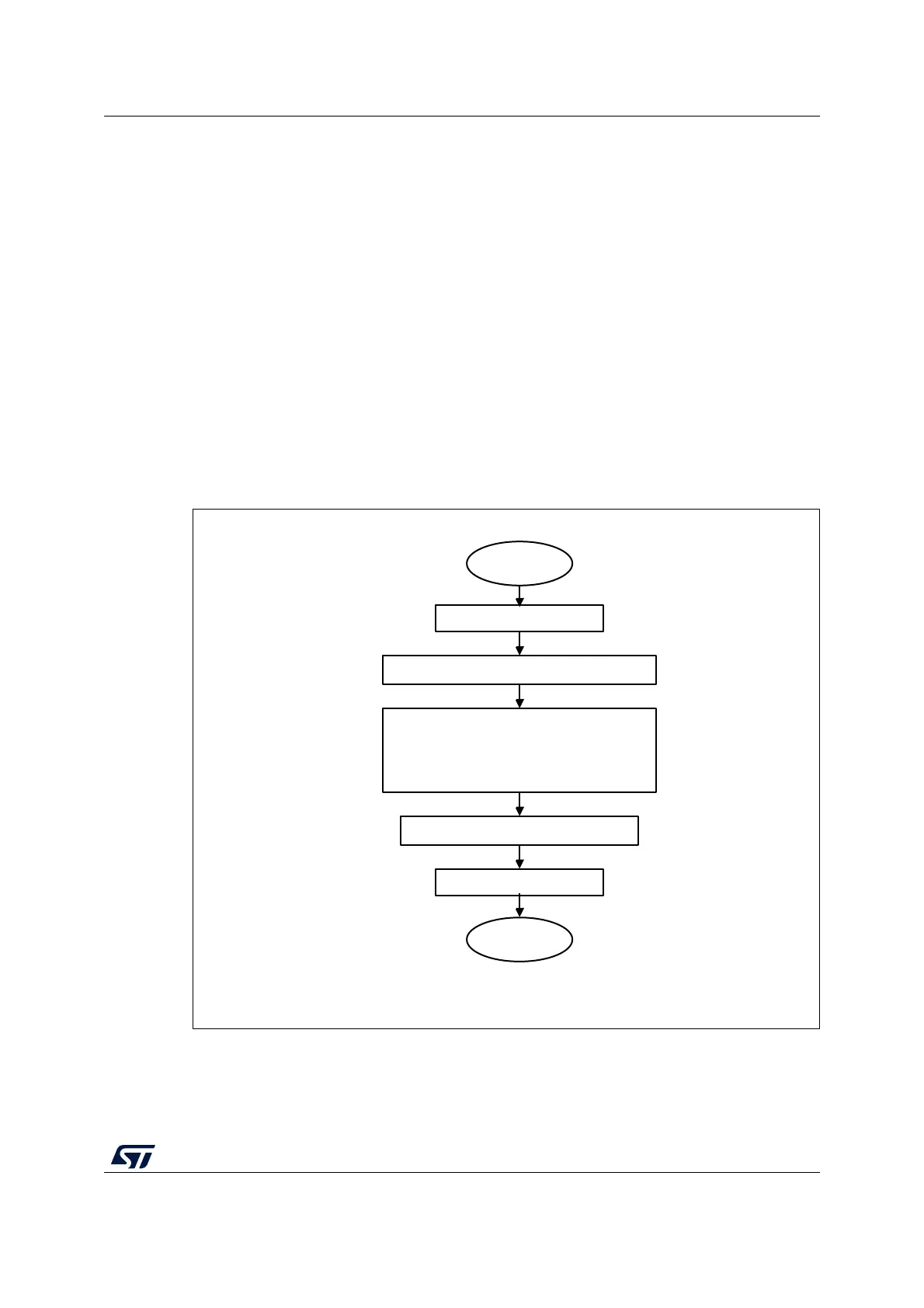
Figure 279. I2C initialization flow
34.4.6 Software reset
A software reset can be performed by clearing the PE bit in the I2C_CR1 register. In that
case I2C lines SCL and SDA are released. Internal states machines are reset and
MS19847V2
Clear PE bit in I2C_CR1
Initial settings
Configure ANFOFF and DNF[3:0] in I2C_CR1
Configure PRESC[3:0],
SDADEL[3:0], SCLDEL[3:0], SCLH[7:0],
SCLL[7:0] in I2C_TIMINGR
Configure NOSTRETCH in I2C_CR1
Set PE bit in I2C_CR1
End