RM0453 Rev 5 663/1450
RM0453 AES hardware accelerator (AES)
694
To resume the processing of a message, proceed as follows:
1. If DMA is used, configure the DMA controller so as to complete the rest of the FIFO IN
and FIFO OUT transfers.
2. Disable the AES peripheral by clearing the EN bit of the AES_CR register.
3. Restore AES_CR register (with correct KEYSIZE) then restore AES_KEYRx registers.
4. Prepare the decryption key as described in Section 23.4.5: AES decryption round key
preparation (only required for ECB or CBC decryption).
5. Restore AES_IVRx registers using the saved configuration (only required in CBC
mode).
6. Enable the AES peripheral by setting the EN bit of the AES_CR register.
7. If DMA is used, enable AES DMA transfers by setting the DMAINEN and DMAOUTEN
bits of the AES_CR register.
23.4.9 AES counter (CTR) mode
Overview
The counter mode (CTR) uses AES as a key-stream generator. The generated keys are
then XOR-ed with the plaintext to obtain the ciphertext.
CTR chaining is defined in NIST Special Publication 800-38A, Recommendation for Block
Cipher Modes of Operation. A typical message construction in CTR mode is given in
Figure 115.
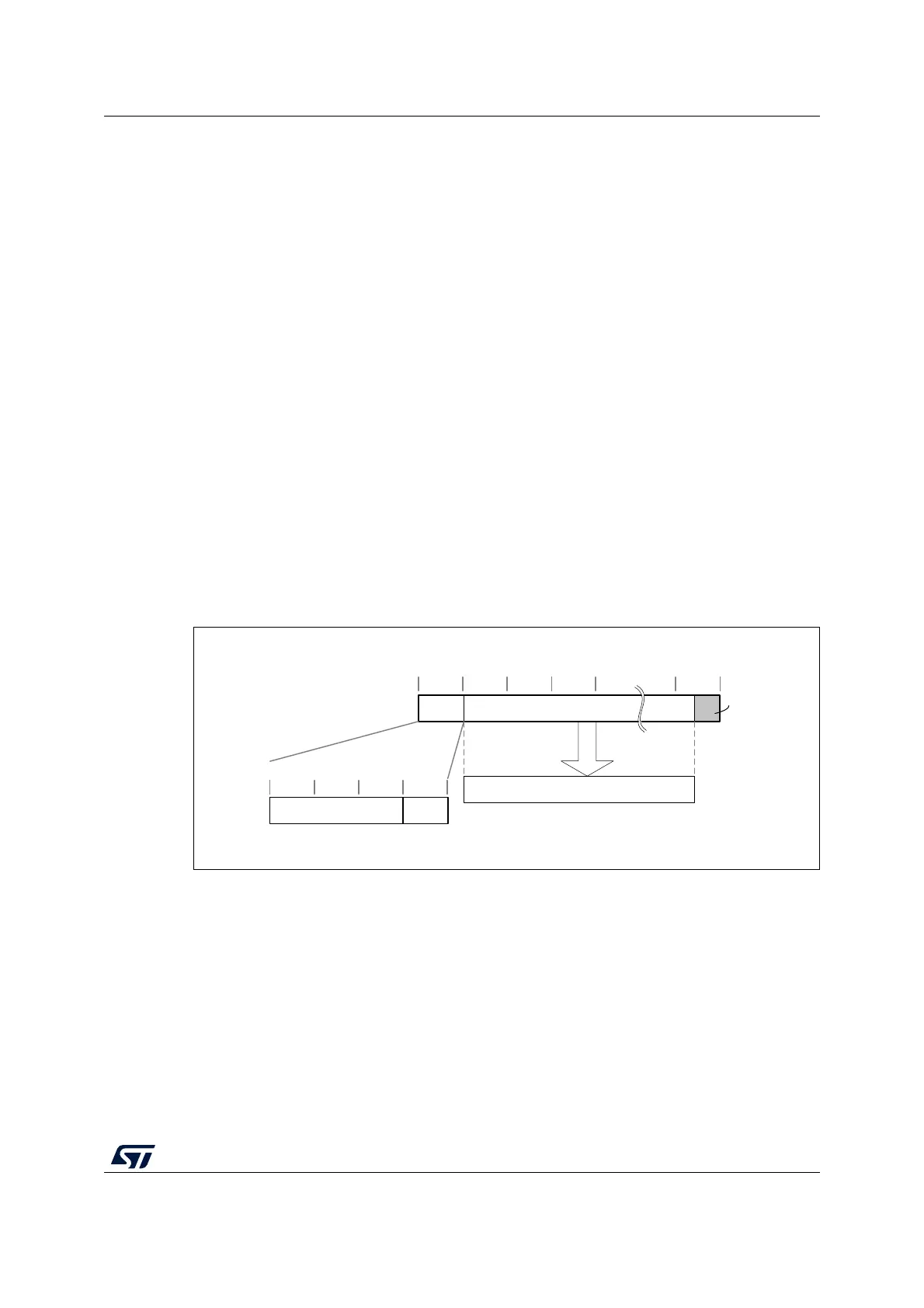
Figure 115. Message construction in CTR mode
The structure of this message is:
• A 16-byte initial counter block (ICB), composed of two distinct fields:
– Initialization vector (IV): a 96-bit value that must be unique for each encryption
cycle with a given key.
– Counter: a 32-bit big-endian integer that is incremented each time a block
processing is completed. The initial value of the counter must be set to 1.
• The plaintext P is encrypted as ciphertext C, with a known length. This length can be
non-multiple of 16 bytes, in which case a plaintext padding is required.
MSv42156V1
16-byte boundaries
ICB Ciphertext (C) 0
4-byte boundaries
CounterInitialization vector (IV)
decrypt
Plaintext (P)
Zero
padding