RM0453 Rev 5 1053/1450
RM0453 Inter-integrated circuit (I2C) interface
1113
By default, it operates in slave mode. The interface automatically switches from slave to
master when it generates a START condition, and from master to slave if an arbitration loss
or a STOP generation occurs, allowing multimaster capability.
Communication flow
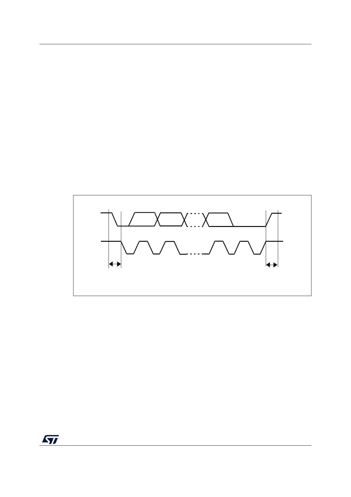
In master mode, the I2C interface initiates a data transfer and generates the clock signal. A
serial data transfer always begins with a START condition and ends with a STOP condition.
Both START and STOP conditions are generated in master mode by software.
In slave mode, the interface is capable of recognizing its own addresses (7- or 10-bit), and
the general call address. The general call address detection can be enabled or disabled by
software. The reserved SMBus addresses can also be enabled by software.
Data and addresses are transferred as 8-bit bytes, MSB first. The first byte(s) following the
START condition contains the address (one in 7-bit mode, two in 10-bit mode). The address
is always transmitted in master mode.
A ninth clock pulse follows the eight clock cycles of a byte transfer, during which the receiver
must send an acknowledge bit to the transmitter (see Figure 277).
Figure 277. I
2
C bus protocol
Acknowledge can be enabled or disabled by software. The I2C interface addresses can be
selected by software.
34.4.5 I2C initialization
Enabling and disabling the peripheral
The I2C peripheral clock must be configured and enabled in the clock controller, then the
I2C can be enabled by setting the PE bit in the I2C_CR1 register.
When the I2C is disabled (PE = 0), the I
2
C performs a software reset. Refer to
Section 34.4.6 for more details.
Noise filters
Before enabling the I2C peripheral by setting the PE bit in I2C_CR1 register, the user must
configure the noise filters, if needed. By default, an analog noise filter is present on the SDA
and SCL inputs. This filter is compliant with the I
2
C specification, which requires the
suppression of spikes with pulse width up to 50 ns in Fast-mode and Fast-mode Plus. The
MS19854V1
SDA
SCL
Start
condition
Stop
condition
MSB ACK
12 89