Inter-integrated circuit (I2C) interface RM0453
1088/1450 RM0453 Rev 5
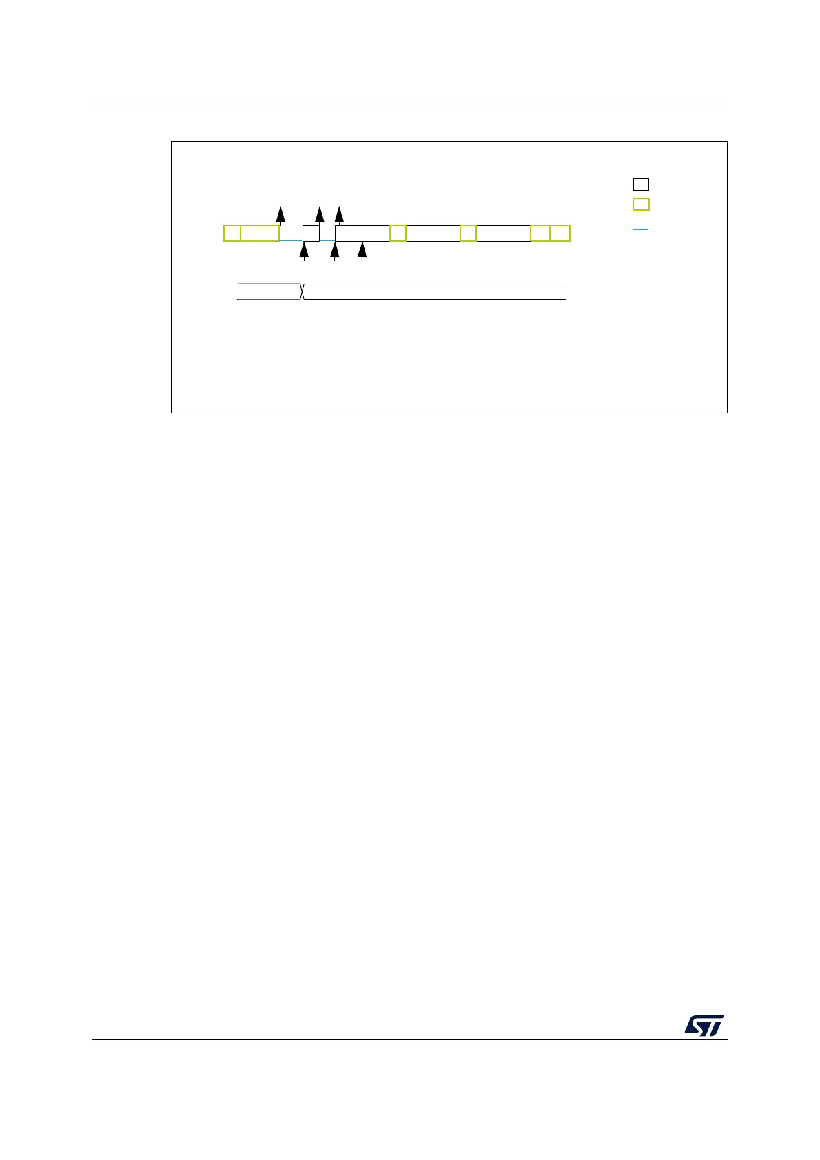
Figure 301. Transfer bus diagrams for SMBus slave transmitter (SBC = 1)
SMBus Slave receiver
When the I2C is used in SMBus mode, SBC must be programmed to ‘1’ to allow the PEC
checking at the end of the programmed number of data bytes. In order to allow the ACK
control of each byte, the reload mode must be selected (RELOAD = 1). Refer to Slave byte
control mode for more details.
In order to check the PEC byte, the RELOAD bit must be cleared and the PECBYTE bit
must be set. In this case, after NBYTES - 1 data have been received, the next received byte
is compared with the internal I2C_PECR register content. A NACK is automatically
generated if the comparison does not match, and an ACK is automatically generated if the
comparison matches, whatever the ACK bit value. Once the PEC byte is received, it is
copied into the I2C_RXDR register like any other data, and the RXNE flag is set.
In the case of a PEC mismatch, the PECERR flag is set and an interrupt is generated if the
ERRIE bit is set in the I2C_CR1 register.
If no ACK software control is needed, the user can program PECBYTE = 1 and, in the same
write operation, program NBYTES with the number of bytes to be received in a continuous
flow. After NBYTES - 1 are received, the next received byte is checked as being the PEC.
Caution: The PECBYTE bit has no effect when the RELOAD bit is set.
MS19869V2
Example SMBus slave transmitter 2 bytes + PEC,
EV1: ADDR ISR: check ADDCODE, program NBYTES=3, set PECBYTE, set ADDRCF
EV2: TXIS ISR: wr data1
EV3: TXIS ISR: wr data2
ADDR
legend:
transmission
reception
SCL stretch
EV1 EV2
TXIS
TXIS
EV3
NBYTES 3
S Address A Adata1
data2
PECANAP