General-purpose timer (TIM2) RM0453
856/1450 RM0453 Rev 5
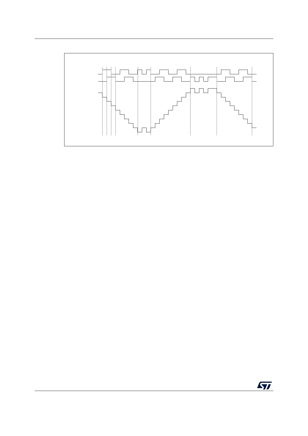
Figure 226. Example of encoder interface mode with TI1FP1 polarity inverted
The timer, when configured in Encoder Interface mode provides information on the sensor’s
current position. Dynamic information can be obtained (speed, acceleration, deceleration)
by measuring the period between two encoder events using a second timer configured in
capture mode. The output of the encoder which indicates the mechanical zero can be used
for this purpose. Depending on the time between two events, the counter can also be read
at regular times. This can be done by latching the counter value into a third input capture
register if available (then the capture signal must be periodic and can be generated by
another timer). when available, it is also possible to read its value through a DMA request
generated by a Real-Time clock.
26.3.16 UIF bit remapping
The IUFREMAP bit in the TIMx_CR1 register forces a continuous copy of the update
interrupt flag (UIF) into bit 31 of the timer counter register’s bit 31 (TIMxCNT[31]). This
permits to atomically read both the counter value and a potential roll-over condition signaled
by the UIFCPY flag. It eases the calculation of angular speed by avoiding race conditions
caused, for instance, by a processing shared between a background task (counter reading)
and an interrupt (update interrupt).
There is no latency between the UIF and UIFCPY flag assertions.
In 32-bit timer implementations, when the IUFREMAP bit is set, bit 31 of the counter is
overwritten by the UIFCPY flag upon read access (the counter’s most significant bit is only
accessible in write mode).
26.3.17 Timer input XOR function
The TI1S bit in the TIM1xx_CR2 register, allows the input filter of channel 1 to be connected
to the output of a XOR gate, combining the three input pins TIMx_CH1 to TIMx_CH3.
The XOR output can be used with all the timer input functions such as trigger or input
capture.
An example of this feature used to interface Hall sensors is given in Section 25.3.25:
Interfacing with Hall sensors on page 773.
TI1
backwardjitter jitter
updown
TI2
Counter
forward forward
MS33108V1
down