RM0453 Rev 5 1213/1450
RM0453 Low-power universal asynchronous receiver transmitter (LPUART)
1253
Selecting the clock source
The choice of the clock source is done through the Clock Control system (see Section Reset
and clock controller (RCC)). The clock source must be selected through the UE bit, before
enabling the LPUART.
The clock source must be selected according to two criteria:
• Possible use of the LPUART in low-power mode
• Communication speed.
The clock source frequency is lpuart_ker_ck.
When the dual clock domain and the wake-up from low-power mode features are supported,
the lpuart_ker_ck clock source can be configured in the RCC (see Section Reset and clock
controller (RCC)). Otherwise, the lpuart_ker_ck is the same as lpuart_pclk.
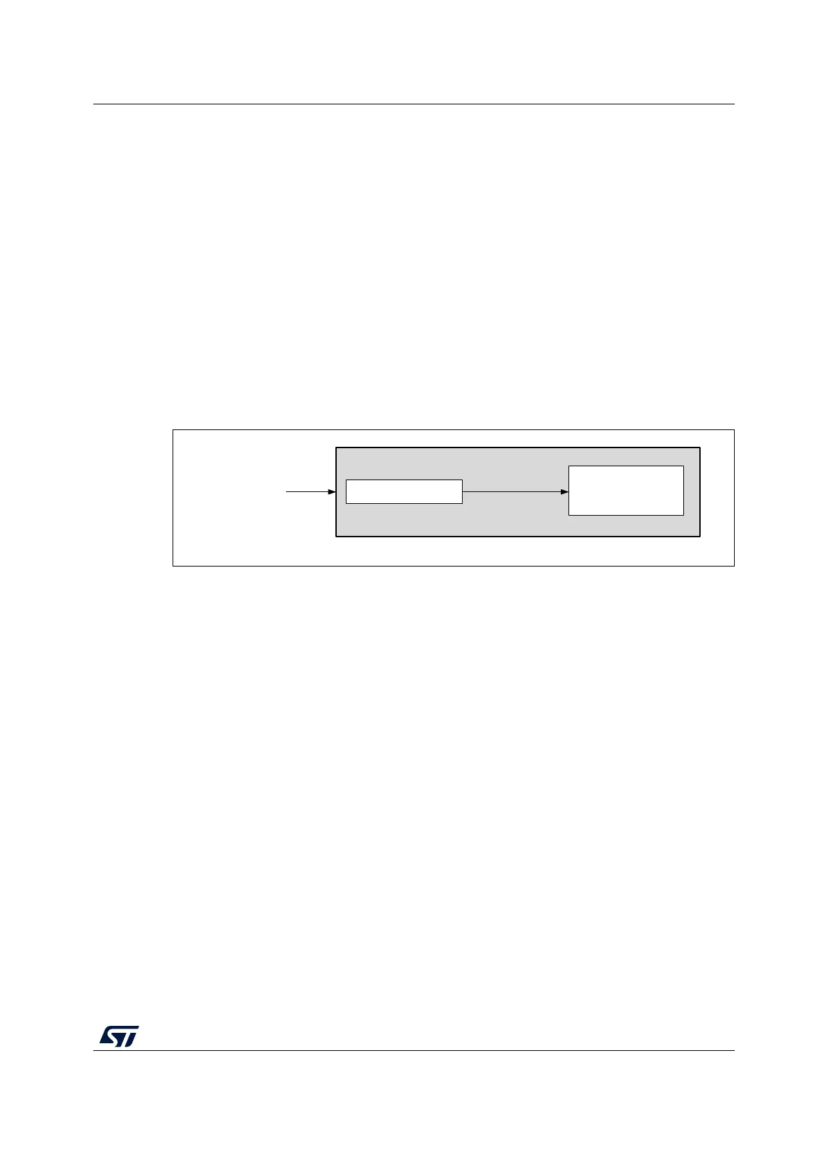
The lpuart_ker_ck can be divided by a programmable factor in the LPUART_PRESC
register.
Figure 337. lpuart_ker_ck clock divider block diagram
Some lpuart_ker_ck sources enable the LPUART to receive data while the MCU is in low-
power mode. Depending on the received data and wake-up mode selection, the LPUART
wakes up the MCU, when needed, in order to transfer the received data by software reading
the LPUART_RDR register or by DMA.
For the other clock sources, the system must be active to enable LPUART communications.
The communication speed range (specially the maximum communication speed) is also
determined by the clock source.
The receiver samples each incoming bit as close as possible to the middle of the bit-period.
Only a single sample is taken of each of the incoming bits.
Note: There is no noise detection for data.
Framing error
A framing error is detected when the stop bit is not recognized on reception at the expected
time, following either a de-synchronization or excessive noise.
When the framing error is detected:
• the FE bit is set by hardware;
• the invalid data is transferred from the Shift register to the LPUART_RDR register.
• no interrupt is generated in case of single byte communication. However this bit rises at
the same time as the RXNE bit which itself generates an interrupt. In case of
MSv40859V1
LPUARTx_PRESC[3:0]
LPUARTx_BRR
register and
oversampling
lpuart_ker_ck_pres
lpuart_ker_ck