RM0453 Rev 5 1223/1450
RM0453 Low-power universal asynchronous receiver transmitter (LPUART)
1253
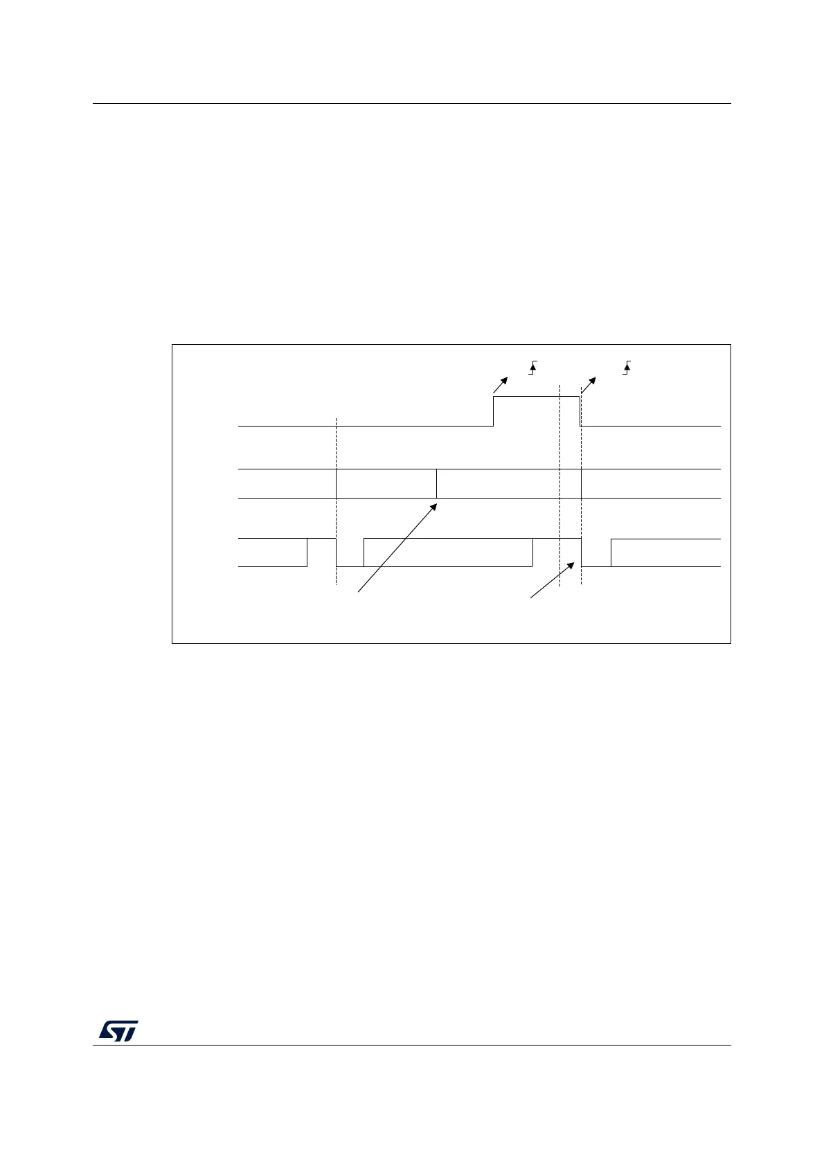
RS232 CTS flow control
If the CTS flow control is enabled (CTSE = 1), then the transmitter checks the CTS input
before transmitting the next frame. If CTS is deasserted (tied low), then the next data is
transmitted (assuming that data is to be transmitted, in other words, if TXE/TXFE = 0), else
the transmission does not occur. When CTS is asserted during a transmission, the current
transmission is completed before the transmitter stops.
When CTSE = 1, the CTSIF status bit is automatically set by hardware as soon as the CTS
input toggles. It indicates when the receiver becomes ready or not ready for communication.
An interrupt is generated if the CTSIE bit in the LPUART_CR3 register is set. Figure 344
shows an example of communication with CTS flow control enabled.
Figure 344. RS232 CTS flow control
Note: For correct behavior, CTS must be deasserted at least 3 LPUART clock source periods
before the end of the current character. In addition it should be noted that the CTSCF flag
may not be set for pulses shorter than 2 x PCLK periods.
RS485 driver enable
The driver enable feature is enabled by setting bit DEM in the LPUART_CR3 control
register. This enables activating the external transceiver control, through the DE (Driver
Enable) signal. The assertion time is the time between the activation of the DE signal and
the beginning of the start bit. It is programmed using the DEAT [4:0] bitfields in the
LPUART_CR1 control register. The deassertion time is the time between the end of the last
stop bit, in a transmitted message, and the de-activation of the DE signal. It is programmed
using the DEDT [4:0] bitfields in the LPUART_CR1 control register. The polarity of the DE
signal can be configured using the DEP bit in the LPUART_CR3 control register.
MSv68793V1
Start
bit
Stop
bit
TX
TDR
CTS
Data 1
Data 2
Stop
bit
Idle
Start
bit
Data 2 Data 3
Data 3
empty empty
CTS
CTS
Transmit data register
Writing data 3 in TDR
Transmission of Data 3 is
delayed until CTS = 0