RM0453 Rev 5 175/1450
RM0453 Sub-GHz radio (SUBGHZ)
227
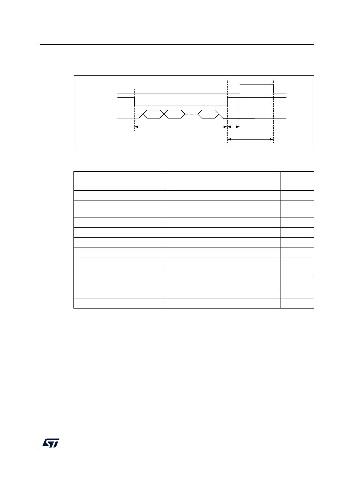
BUSY timing is shown in the figure below.
Figure 16. Sub-GHz radio BUSY timing
For the different mode transitions, typical busy timing values are given in the table below.
5.8 Sub-GHz radio SPI interface
The sub-GHz radio SPI slave interface gives access to the sub-GHz radio configuration,
registers and buffer memory, through SPI commands. It is connected to the SUBGHZSPI
master interface peripheral on the CPU bus matrix.
For a write access, an opcode byte is sent followed by sending the command parameter
bytes.
For a read access, an opcode byte is sent followed by receiving data bytes.
Table 33. Operation mode transition BUSY switching time
Mode transition SPI command (sub-GHz radio event)
t
SWMODE
typical (μs)
Sleep-to-Standby (no data retention) SPI NSS low 20 μs 3500
Sleep-to-Standby (with data
retention)
SPI NSS low 20 μs (RTC end-of-count) 340
Standby-to-Standby with HSE32 Set_Standby() 31
Standby (HSE32 off)-to-FS
(1)
1. When entering FS mode, BUSY is cleared to 0 when RF-PLL is locked.
Set_Fs() 50
Standby (HSE32 off)-to-TX
(2)
2. When entering TX mode, BUSY is cleared to 0 when the PA ramps up and the transmission of
preamble starts.
all Set_Tx() 126
Standby (HSE32 off)-to-RX
(3)
3. When entering RX mode, BUSY is cleared to 0 when the receiver is ready to receive data.
Set_Rx(), Set_Cad() 83
Standby (HSE32 on)-to-FS
(1)
Set_Fs() 40
Standby (HSE32 on)-to-TX
(2)
all Set_Tx() 105
Standby (HSE32 on)-to-RX
(3)
Set_Rx(), Set_Cad() 62
FS-to-TX
(2)
all Set_Tx() 76
FS-to-RX
(3)
Set_Rx(), Set_Cad() 41
MSv64330V1
Opcode
Param 1 Param n
t
SWMODE
t
SW
BUSY
NSS
SPI
Write command