General-purpose timers (TIM16/TIM17) RM0453
904/1450 RM0453 Rev 5
1. Select the proper TI2[x] source (internal or external) with the TI2SEL[3:0] bits in the
TIMx_TISEL register.
2. Configure channel 2 to detect rising edges on the TI2 input by writing CC2S = ‘01’ in
the TIMx_CCMR1 register.
3. Configure the input filter duration by writing the IC2F[3:0] bits in the TIMx_CCMR1
register (if no filter is needed, keep IC2F=0000).
4. Select rising edge polarity by writing CC2P=0 in the TIMx_CCER register.
5. Configure the timer in external clock mode 1 by writing SMS=111 in the TIMx_SMCR
register.
6. Select TI2 as the trigger input source by writing TS=00110 in the TIMx_SMCR register.
7. Enable the counter by writing CEN=1 in the TIMx_CR1 register.
Note: The capture prescaler is not used for triggering, so it does not need to be configured.
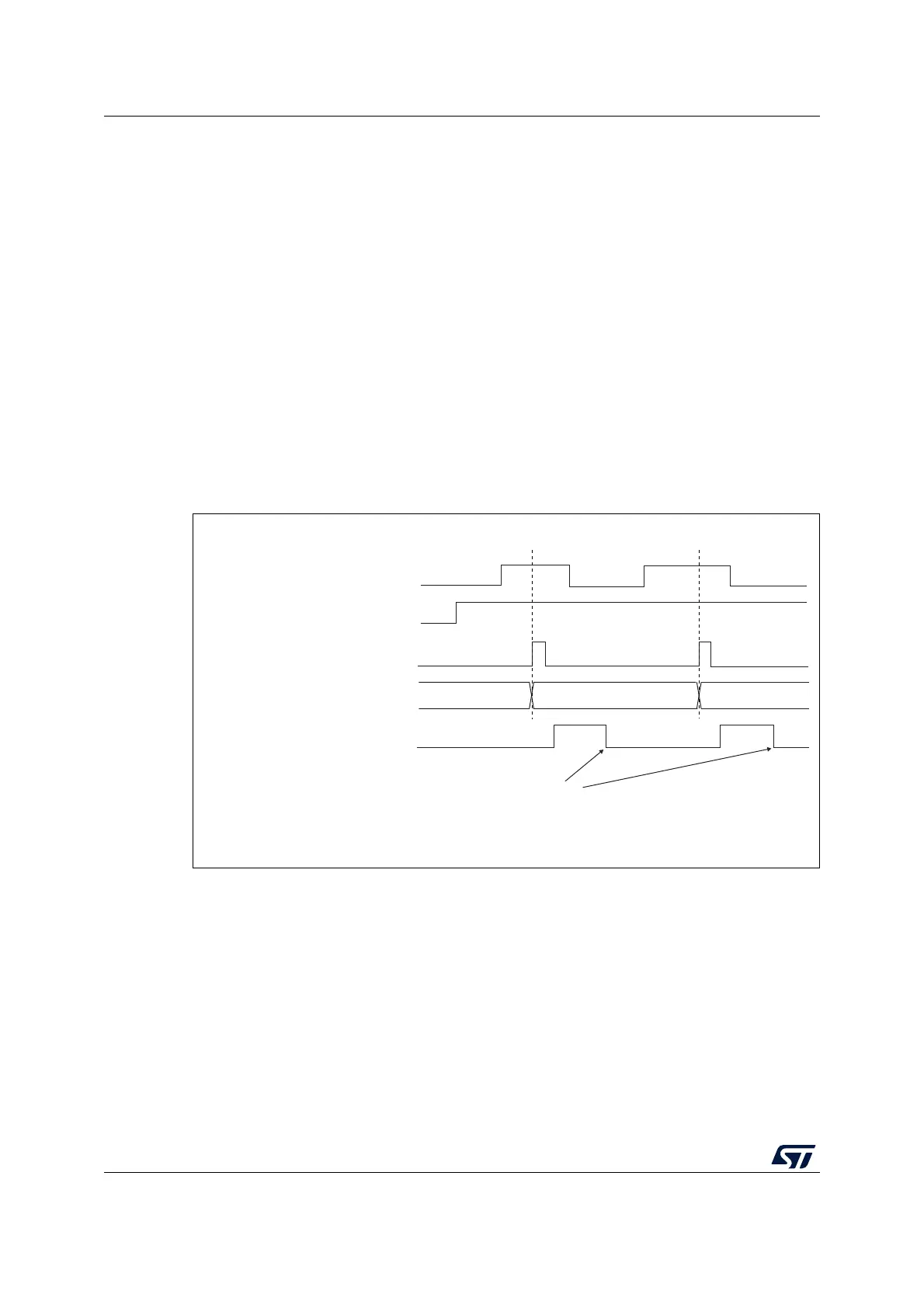
When a rising edge occurs on TI2, the counter counts once and the TIF flag is set.
The delay between the rising edge on TI2 and the actual clock of the counter is due to the
resynchronization circuit on TI2 input.
Figure 249. Control circuit in external clock mode 1
27.3.5 Capture/compare channels
Each Capture/Compare channel is built around a capture/compare register (including a
shadow register), a input stage for capture (with digital filter, multiplexing and prescaler) and
an output stage (with comparator and output control).
Figure 250 to Figure 252 give an overview of one Capture/Compare channel.
The input stage samples the corresponding TIx input to generate a filtered signal TIxF.
Then, an edge detector with polarity selection generates a signal (TIxFPx) which can be
used as trigger input by the slave mode controller or as the capture command. It is
prescaled before the capture register (ICxPS).
Counter clock = CK_CNT = CK_PSC
Counter register
35 3634
TI2
CNT_EN
TIF
Write TIF=0
MS31087V2