Inter-integrated circuit (I2C) interface RM0453
1054/1450 RM0453 Rev 5
user can disable this analog filter by setting the ANFOFF bit, and/or select a digital filter by
configuring the DNF[3:0] bit in the I2C_CR1 register.
When the digital filter is enabled, the level of the SCL or the SDA line is internally changed
only if it remains stable for more than DNF x I2CCLK periods. This allows spikes with a
programmable length of 1 to 15 I2CCLK periods to be suppressed.
Caution: The filter configuration cannot be changed when the I2C is enabled.
I2C timings
The timings must be configured to guarantee correct data hold and setup times, in master
and slave modes. This is done by programming the PRESC[3:0], SCLDEL[3:0] and
SDADEL[3:0] bits in the I2C_TIMINGR register.
The STM32CubeMX tool calculates and provides the I2C_TIMINGR content in the I2C
configuration window.
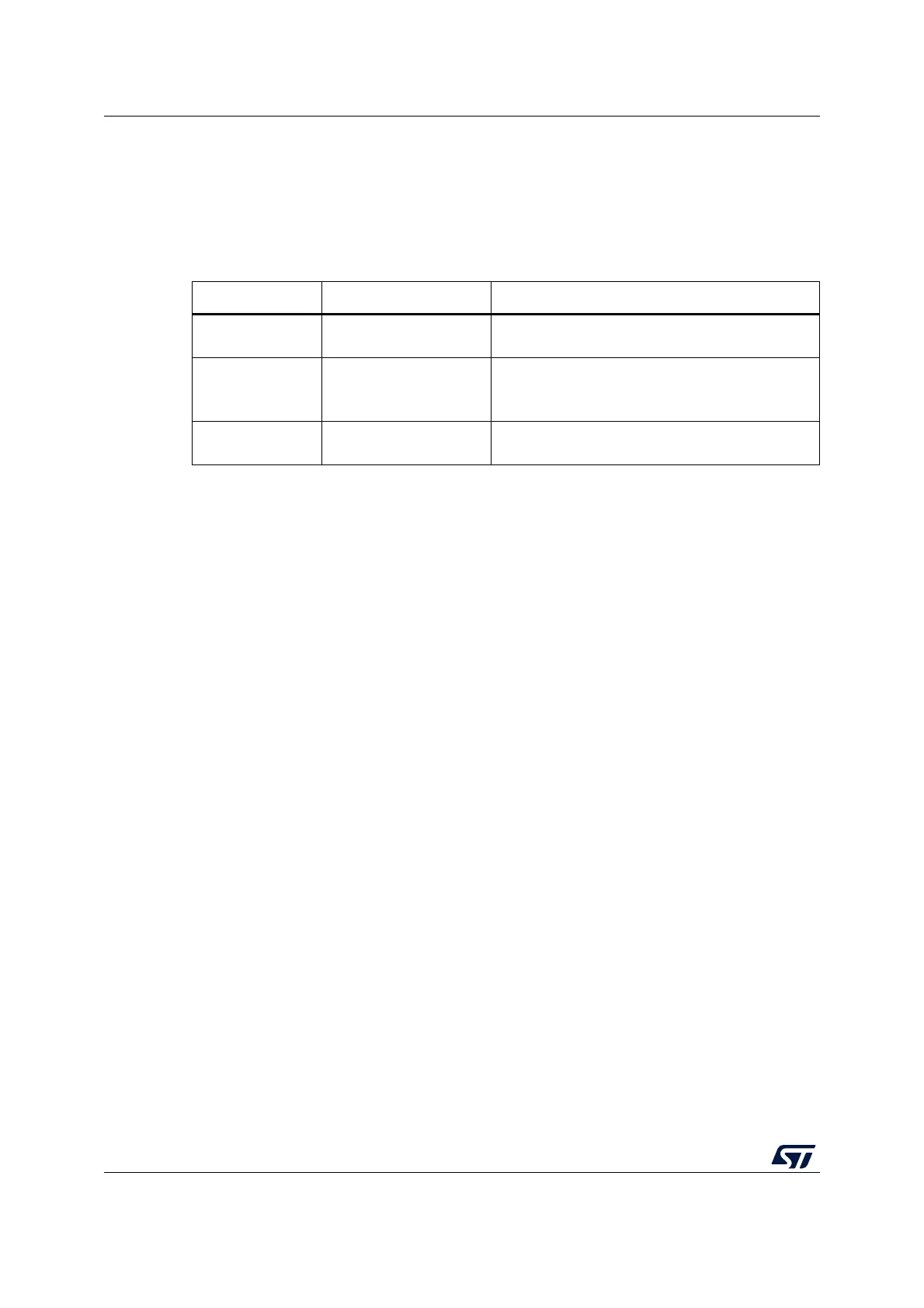
Table 225. Comparison of analog vs. digital filters
- Analog filter Digital filter
Pulse width of
suppressed spikes
≥ 50 ns
Programmable length, from one to fifteen I2C
peripheral clocks
Benefits Available in Stop mode
– Programmable length: extra filtering capability
versus standard requirements
– Stable length
Drawbacks
Variation vs. temperature,
voltage, process
Wake-up from Stop mode on address match is not
available when digital filter is enabled