RM0453 Rev 5 837/1450
RM0453 General-purpose timer (TIM2)
892
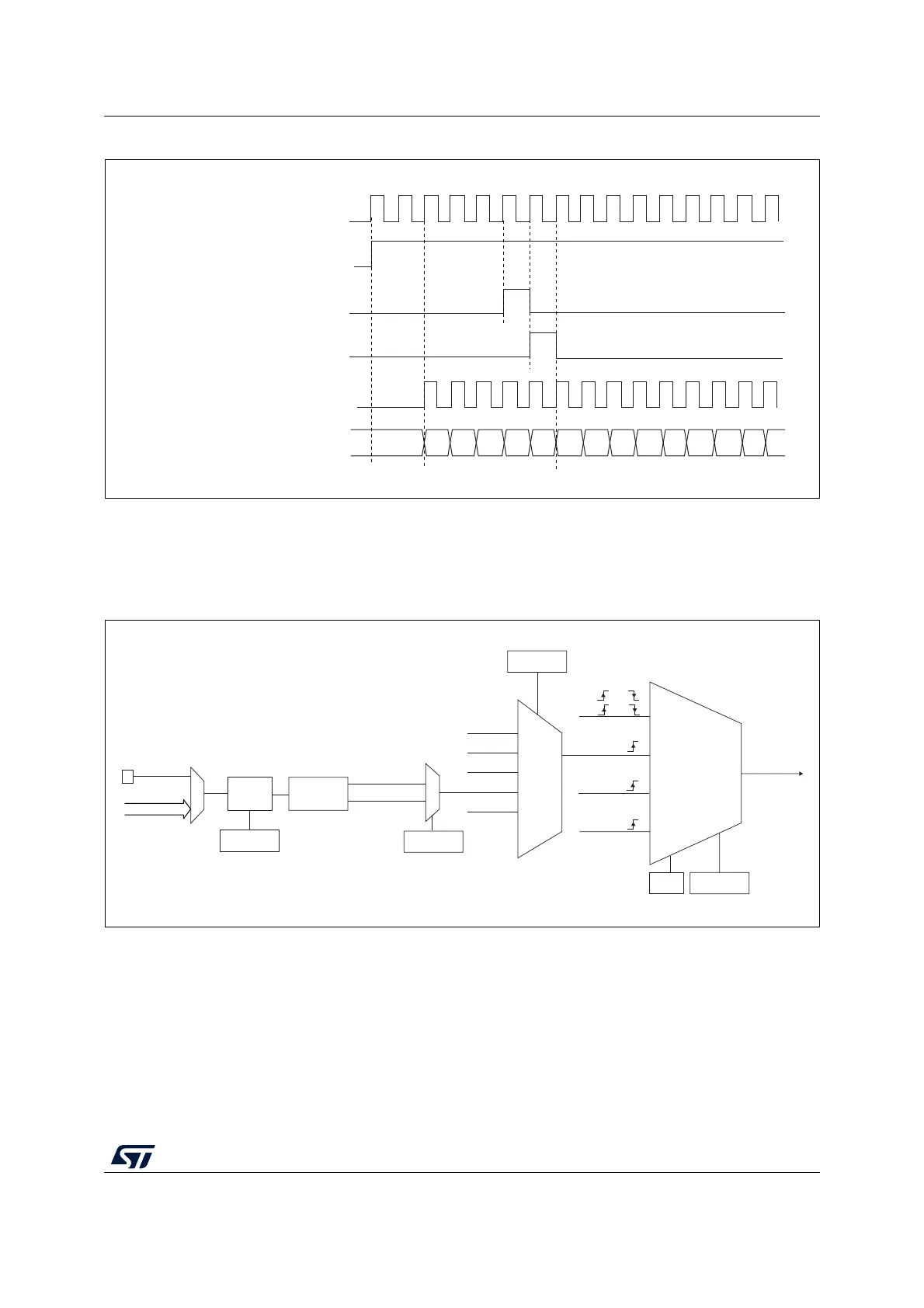
Figure 208. Control circuit in normal mode, internal clock divided by 1
External clock source mode 1
This mode is selected when SMS=111 in the TIMx_SMCR register. The counter can count at
each rising or falling edge on a selected input.
Figure 209. TI2 external clock connection example
1. Codes ranging from 01000 to 11111: ITRy.
For example, to configure the upcounter to count in response to a rising edge on the TI2
input, use the following procedure:
1. Select the proper TI2x source (internal or external) with the TI2SEL[3:0] bits in the
TIMx_TISEL register.
2. Configure channel 2 to detect rising edges on the TI2 input by writing CC2S= ‘01 in the
TIMx_CCMR1 register.
3. Configure the input filter duration by writing the IC2F[3:0] bits in the TIMx_CCMR1
register (if no filter is needed, keep IC2F=0000).
Internal clock
Counter clock = CK_CNT = CK_PSC
Counter register
CEN=CNT_EN
UG
CNT_INIT
MS31085V2
00 02
03
04 05
06 0732
33
34 35 36
31
01
MSv40117V1
External clock
mode 1
Internal clock
mode
CK_PSC
TIMx_SMCR
SMS[2:0]
ITRx
TI1_ED
TI1FP1
TI2FP2
TIMx_SMCR
TS[4:0]
TI2[0]
0
1
TIMx_CCER
CC2P
TIMx_CCMR1
Edge
detector
TI2F_Rising
TI2F_Falling
00110
000xx
00100
00101
Filter
ICF[3:0]
(internal clock)
Encoder
mode
ETRF
00111
External clock
mode 2
ECE
TI2[1..15]
TI2
TRGI
ETRF
CK_INT
TI1F or
TI2F or
or
TIMx_CH2
(1)