Analog-to-digital converter (ADC) RM0453
538/1450 RM0453 Rev 5
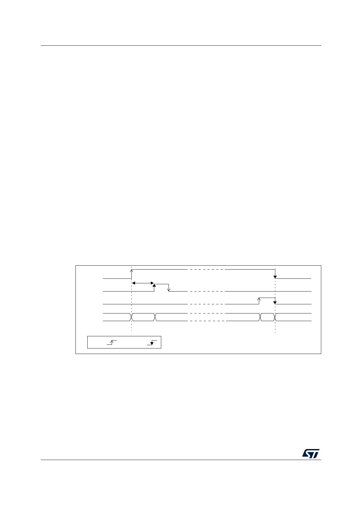
Two control bits are used to enable or disable the ADC:
• Set ADEN = 1 to enable the ADC. The ADRDY flag is set as soon as the ADC is ready
for operation.
• Set ADDIS = 1 to disable the ADC and put the ADC in power down mode. The ADEN
and ADDIS bits are then automatically cleared by hardware as soon as the ADC is fully
disabled.
Conversion can then start either by setting ADSTART to 1 (refer to Section 18.4: Conversion
on external trigger and trigger polarity (EXTSEL, EXTEN) on page 547) or when an external
trigger event occurs if triggers are enabled.
Follow this procedure to enable the ADC:
1. Clear the ADRDY bit in ADC_ISR register by programming this bit to 1.
2. Set ADEN = 1 in the ADC_CR register.
3. Wait until ADRDY = 1 in the ADC_ISR register (ADRDY is set after the ADC startup
time). This can be handled by interrupt if the interrupt is enabled by setting the
ADRDYIE bit in the ADC_IER register.
Follow this procedure to disable the ADC:
1. Check that ADSTART = 0 in the ADC_CR register to ensure that no conversion is
ongoing. If required, stop any ongoing conversion by writing 1 to the ADSTP bit in the
ADC_CR register and waiting until this bit is read at 0.
2. Set ADDIS = 1 in the ADC_CR register.
3. If required by the application, wait until ADEN = 0 in the ADC_CR register, indicating
that the ADC is fully disabled (ADDIS is automatically reset once ADEN = 0).
4. Clear the ADRDY bit in ADC_ISR register by programming this bit to 1 (optional).
Figure 61. Enabling/disabling the ADC
Note: In Auto-off mode (AUTOFF = 1) the power-on/off phases are performed automatically, by
hardware and the ADRDY flag is not set.
When the bus clock is much faster than the analog ADC_CK clock, a minimum delay of ten
analog ADC_CK cycles must be respected between ADEN and ADDIS bit settings.
MS30264V2
t
STAB
ADEN
ADRDY
ADDIS
ADC
OFF Startup RDY CONVERTING CH RDY
OFF
by H/W
by S/W
REQ
-OF
stat