RM0453 Rev 5 1085/1450
RM0453 Inter-integrated circuit (I2C) interface
1113
Packet error checking
PEC calculation is enabled by setting the PECEN bit in the I2C_CR1 register. Then the PEC
transfer is managed with the help of a hardware byte counter: NBYTES[7:0] in the I2C_CR2
register. The PECEN bit must be configured before enabling the I2C.
The PEC transfer is managed with the hardware byte counter, so the SBC bit must be set
when interfacing the SMBus in slave mode. The PEC is transferred after NBYTES - 1 data
have been transferred when the PECBYTE bit is set and the RELOAD bit is cleared. If
RELOAD is set, PECBYTE has no effect.
Caution: Changing the PECEN configuration is not allowed when the I2C is enabled.
Timeout detection
The timeout detection is enabled by setting the TIMOUTEN and TEXTEN bits in the
I2C_TIMEOUTR register. The timers must be programmed in such a way that they detect a
timeout before the maximum time given in the SMBus specification.
• t
TIMEOUT
check
To enable the t
TIMEOUT
check, the 12-bit TIMEOUTA[11:0] bits must be programmed
with the timer reload value, to check the t
TIMEOUT
parameter. The TIDLE bit must be
configured to ‘0’ to detect the SCL low level timeout.
Then the timer is enabled by setting the TIMOUTEN in the I2C_TIMEOUTR register.
If SCL is tied low for a time greater than (TIMEOUTA + 1) x 2048 x t
I2CCLK
, the
TIMEOUT flag is set in the I2C_ISR register.
Refer to Table 233.
Caution: Changing the TIMEOUTA[11:0] bits and TIDLE bit configuration is not allowed when the
TIMEOUTEN bit is set.
• t
LOW:SEXT
and t
LOW:MEXT
check
Depending on if the peripheral is configured as a master or as a slave, The 12-bit
TIMEOUTB timer must be configured in order to check t
LOW:SEXT
for a slave and
t
LOW:MEXT
for a master. As the standard specifies only a maximum, the user can choose
the same value for the both.
Then the timer is enabled by setting the TEXTEN bit in the I2C_TIMEOUTR register.
If the SMBus peripheral performs a cumulative SCL stretch for a time greater than
(TIMEOUTB + 1) x 2048 x t
I2CCLK
, and in the timeout interval described in Bus idle
detection section, the TIMEOUT flag is set in the I2C_ISR register.
Refer to Table 234
Caution: Changing the TIMEOUTB configuration is not allowed when the TEXTEN bit is set.
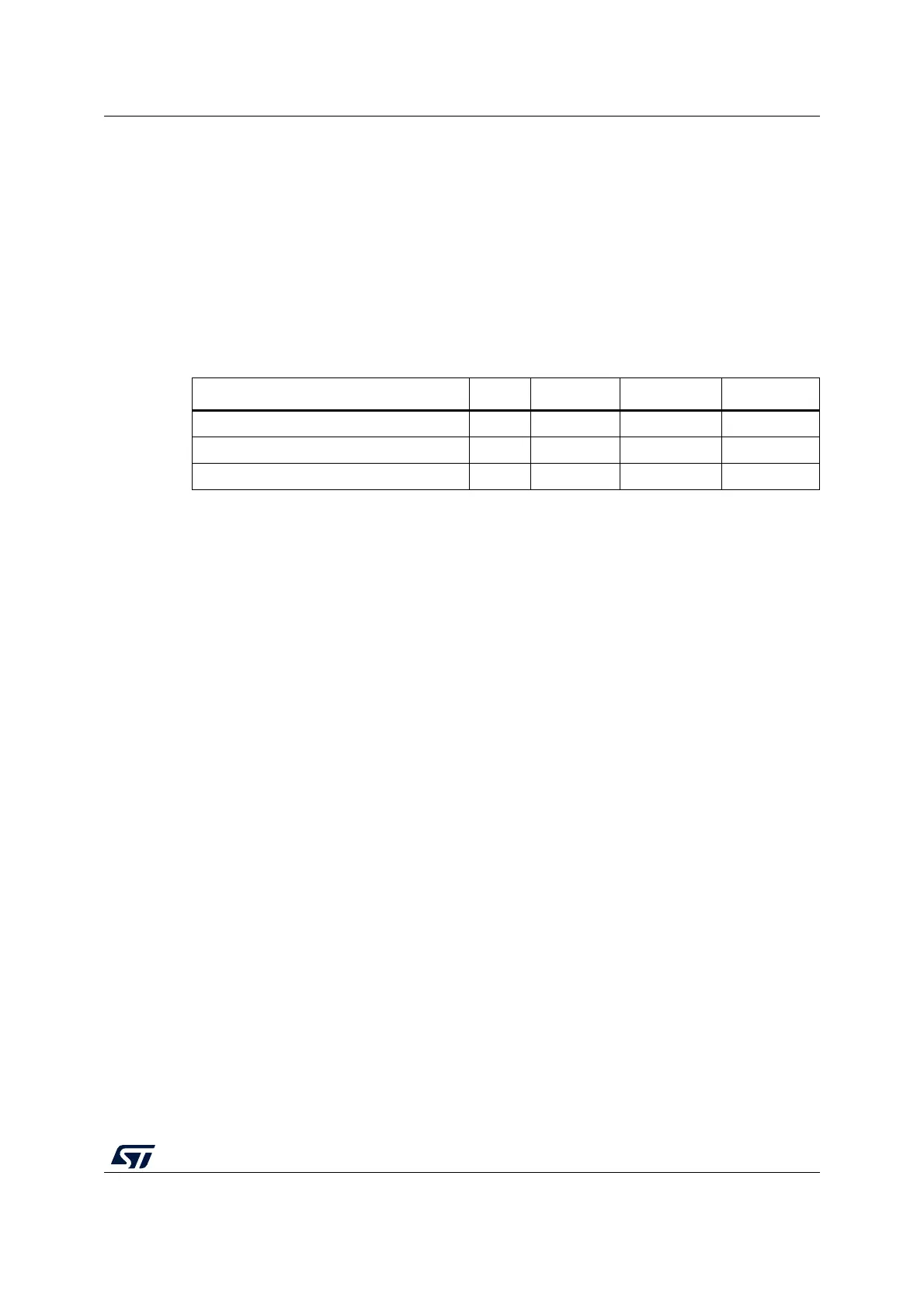
Table 232. SMBus with PEC configuration
Mode SBC bit RELOAD bit AUTOEND bit PECBYTE bit
Master Tx/Rx NBYTES + PEC+ STOP x 0 1 1
Master Tx/Rx NBYTES + PEC + ReSTART x 0 0 1
Slave Tx/Rx with PEC 1 0 x 1