RM0453 Rev 5 387/1450
RM0453 Inter-processor communication controller (IPCC)
399
The channel operation mode must be known to both processors. A common parameter can
be used to indicate the channel transfer mode and must also be located in a known common
area. This parameter is not available from the IPCC.
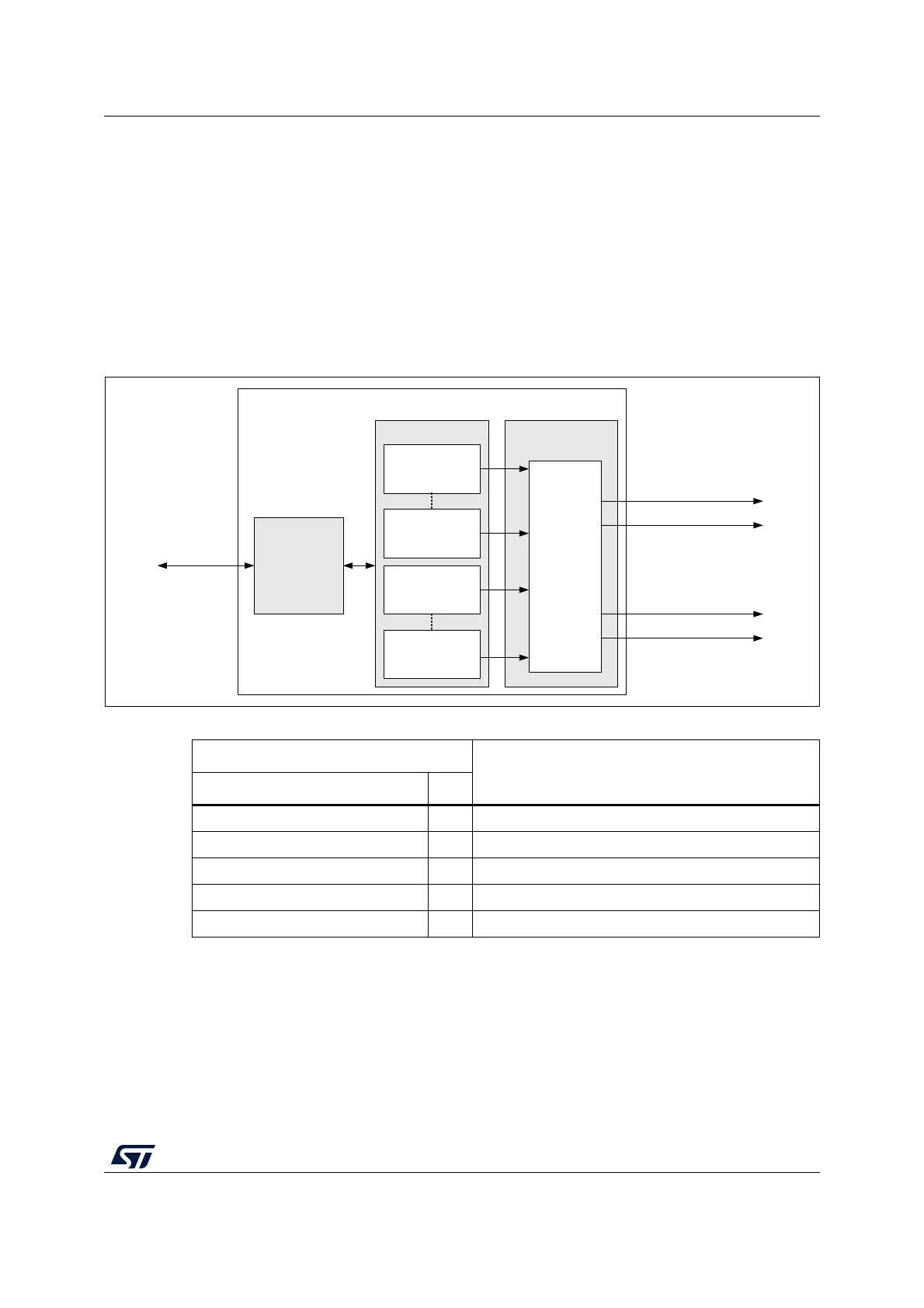
9.3.1 IPCC block diagram
The IPCC (see Figure 36) consists of the following subblocks:
• Status block, containing the channel status
• IPCC interface block, providing AHB access to the channel status registers
• Interrupt interface block, providing control for the interrupts
Figure 36. IPCC block diagram
9.3.2 IPCC Simplex channel mode
In Simplex channel mode, a dedicated memory location (used to transfer data in a single
direction) is assigned to the communication data. The associated channel N control bits
(see Table 68) are used to manage the transfer from the sending to the receiving processor.
MS42429V1
IPCC
INTERRUPT
GENERATION
ipcc_tx_free_int0
ipcc_rx_occupied_int0
IPCC STATUS
1TO2
STATUS
Channel 1
ipcc_tx_free_int1
ipcc_rx_occupied_int1
1TO2
STATUS
Channel N
Interrupt
generation
IPCC
INTERFACE
AHB slave
2TO1
STATUS
Channel 1
2TO1
STATUS
Channel N
Table 67. IPCC interface signals
Signal
Description
Name Type
AHB slave I/O AHB register access bus
ipcc_tx_free_int1 O TX free interrupt to processor 1
ipcc_rx_occupied_int1 O RX occupied interrupt to processor 1
ipcc_tx_free_int2 O TX free interrupt to processor 2
ipcc_rx_occupied_int2 O RX occupied interrupt to processor 2