Embedded flash memory (FLASH) RM0453
118/1450 RM0453 Rev 5
RSSLIB_PFUNC->CloseExitHDP(RSSLIB_HDP_AREA1, 0x8020000);
4.6 Flash memory protection
The main flash memory can be protected against external accesses with the readout
protection (RDP). The pages can also be protected against unwanted write (WRP) due to
loss of program counter context. The write protection WRP granularity is 2 Kbytes.
Apart from the RDP and WRP, the flash memory can also be protected against read and
write from third parties (PCROP). The PCROP granularity is 1 Kbyte.
Part of the flash main memory can be secured, granting exclusive access to this part of the
memory to CPU2.
4.6.1 Readout protection (RDP)
The readout protection is activated by setting the RDP option byte and performing an option
byte programming with OPTSTRT followed by a OBL_LAUNCH, POR or wake-up from
Standby or Shutdown mode. The readout protection protects the main flash memory, the
option bytes, the backup registers (TAMP_BKPxR in TAMP) and SRAM2.
There is no exception while the debugger is connected.
There are three levels of readout protection from no protection (level 0) to maximum
protection or no debug (level 2).
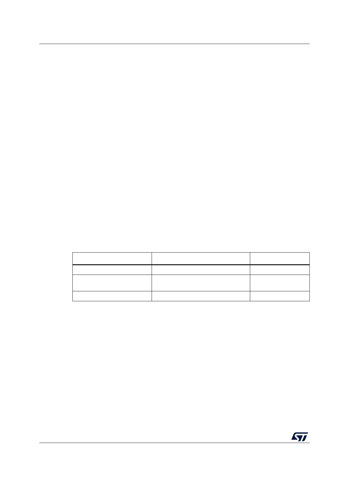
The flash memory is protected when the RDP option byte and its complement contain the
pair of values shown in the table below.
The system memory area is read accessible whatever the protection level. It is never
accessible for program/erase operation.
Level 0: no protection
Read, program and erase operations into the main flash memory area are possible. The
option bytes, SRAM2 and backup registers are also accessible by all operations.
Level 1: readout protection
This is the default protection level when the RDP option byte is erased. It is defined as well
when the RDP value is at any value different from 0xAA and 0xCC, or even if the
complement is not correct.
• User mode
The code executing in user mode (Boot flash) can access the main flash memory,
option bytes, SRAM2 and backup registers with all operations.
Table 18. Flash memory readout protection status
RDP byte value RDP complement value RDP level
0xAA 0x55 Level 0
Any value except 0xAA or 0xCC
Any value (not necessarily
complementary), except 0x55 and 0x33
Level 1 (default)
0xCC 0x33 Level 2