Debug support (DBG) RM0453
1372/1450 RM0453 Rev 5
The topology for the CoreSight components in the CPU1 subsystem is shown in Figure 391.
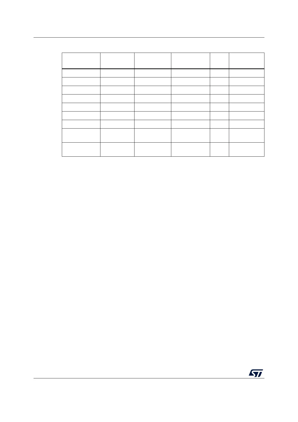
Table 277. CPU1 ROM table
Address
in ROM table
Component
name
Component
base address
Component
address offset
Size
(bytes)
Entry
0xE00FF000 SCS 0xE000E000 0xFFF0F000 4 K 0xFFF0F003
0xE00FF004 DWT 0xE0001000 0xFFF02000 4 K 0xFFF02003
0xE00FF008 FPB 0xE0002000 0xFFF03000 4 K 0xFFF03003
0xE00FF00C ITM 0xE0000000 0xFFF01000 4 K 0xFFF01003
0xE00FF010 TPIU 0xE0040000 0xFFF41000 4 K 0xFFF41003
0xE00FF014 CTI 0xE0043000 0xFFF44000 4 K 0xFFF44003
0xE00FF018 Top of table - - - 0x00000000
0xE00FF01C to
0xE00FFFC8
Reserved - - - 0x00000000
0xE00FFFCC to
0xE00FFFFC
ROM
table registers
- - - See Table 277