Low-power universal asynchronous receiver transmitter (LPUART) RM0453
1208/1450 RM0453 Rev 5
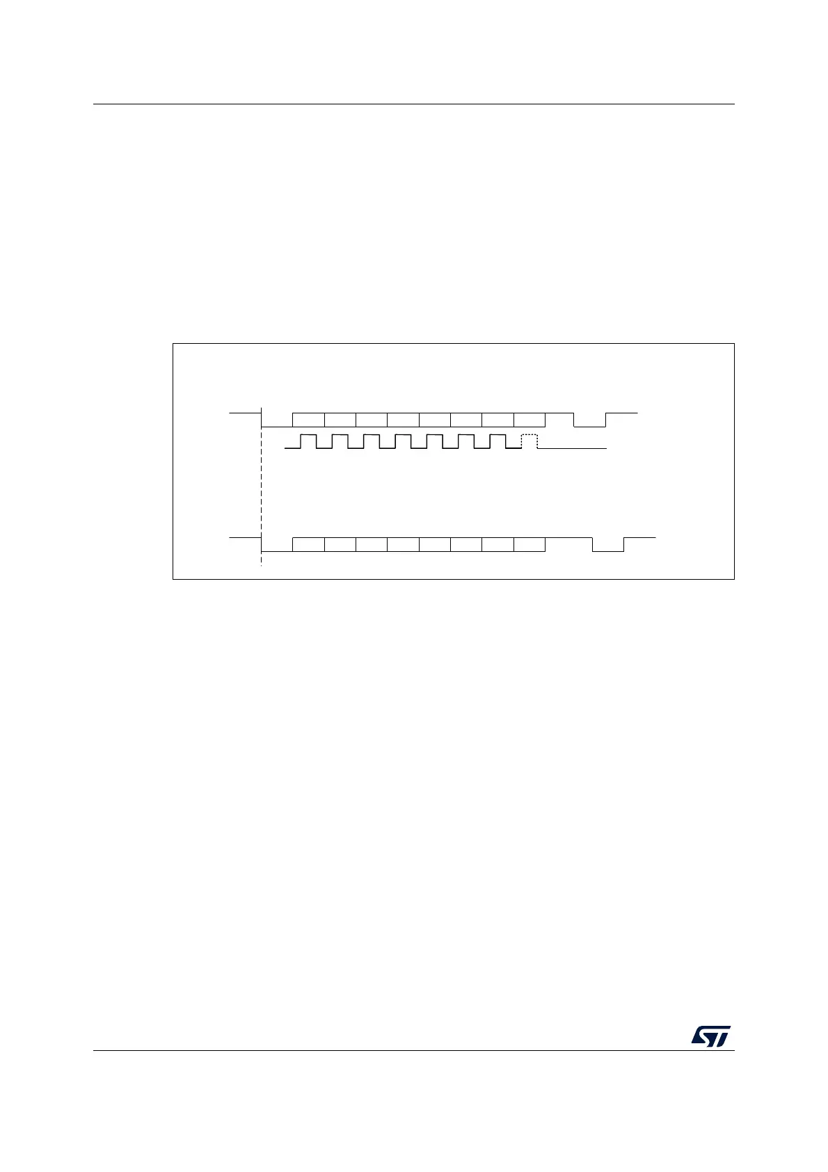
Configurable stop bits
The number of stop bits to be transmitted with every character can be programmed in
LPUART_CR2 (bits 13,12).
• 1 stop bit: This is the default value of number of stop bits.
• 2 Stop bits: This is supported by normal LPUART, Single-wire and Modem modes.
An idle frame transmission includes the stop bits.
A break transmission is 10 low bits (when M[1:0] = ‘00’) or 11 low bits (when M[1:0] = ‘01’) or
9 low bits (when M[1:0] = ‘10’) followed by 2 stop bits. It is not possible to transmit long
breaks (break of length greater than 9/10/11 low bits).
Figure 335. Configurable stop bits
Character transmission procedure
To transmit a character, follow the sequence below:
1. Program the M bits in LPUART_CR1 to define the word length.
2. Select the desired baud rate using the LPUART_BRR register.
3. Program the number of stop bits in LPUART_CR2.
4. Enable the LPUART by writing the UE bit in LPUART_CR1 register to ‘1’.
5. Select DMA enable (DMAT) in LPUART_CR3 if Multi buffer Communication is to take
place. Configure the DMA register as explained in Section 36.4.12: Continuous
communication using DMA and LPUART.
6. Set the TE bit in LPUART_CR1 to send an idle frame as first transmission.
7. Write the data to send in the LPUART_TDR register. Repeat this operation for each
data to be transmitted in case of single buffer.
– When FIFO mode is disabled, writing a data in the LPUART_TDR clears the TXE
flag.
– When FIFO mode is enabled, writing a data in the LPUART_TDR adds one data to
the TXFIFO. Write operations to the LPUART_TDR are performed when TXFNF flag
is set. This flag remains set until the TXFIFO is full.
8. When the last data is written to the LPUART_TDR register, wait until TC = 1. This
indicates that the transmission of the last frame is complete.
– When FIFO mode is disabled, this indicates that the transmission of the last frame is
complete.
MS31885V1
8-bit Word length (M[1:0]=00 bit is reset)
** LBCL bit controls last data clock pulse
Bit7Start bit
Stop
bit
Next
start
bit
Possible
parity bit
Data frame
Next data frame
CLOCK
**
a) 1 Stop bit
b) 2 Stop bits
Bit6Bit5Bit4Bit3Bit2Bit1Bit0
Next data frame
Bit7Start bit
2
Stop
bits
Next
start
bit
Possible
parity bit
Data frame
Bit6Bit5Bit4Bit3Bit2Bit1Bit0