Universal synchronous/asynchronous receiver transmitter (USART/UART) RM0453
1140/1450 RM0453 Rev 5
35.5.12 USART parity control
Parity control (generation of parity bit in transmission and parity checking in reception) can
be enabled by setting the PCE bit in the USART_CR1 register. Depending on the frame
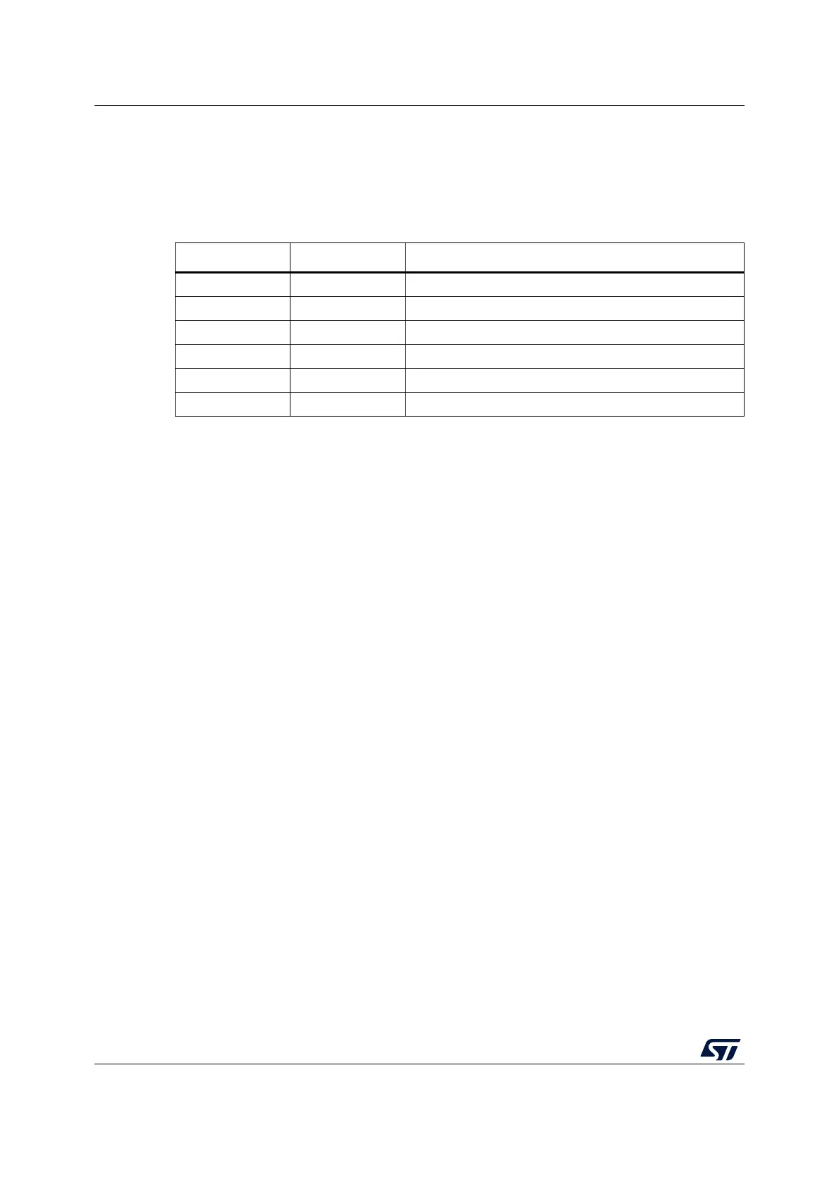
length defined by the M bits, the possible USART frame formats are as listed in Table 243.
Even parity
The parity bit is calculated to obtain an even number of “1s” inside the frame of the 6, 7 or 8
LSB bits (depending on M bit values) and the parity bit.
As an example, if data = 00110101 and 4 bits are set, the parity bit is equal to 0 if even parity
is selected (PS bit in USART_CR1 = 0).
Odd parity
The parity bit is calculated to obtain an odd number of “1s” inside the frame made of the 6, 7
or 8 LSB bits (depending on M bit values) and the parity bit.
As an example, if data = 00110101 and 4 bits set, then the parity bit is equal to 1 if odd parity
is selected (PS bit in USART_CR1 = 1).
Parity checking in reception
If the parity check fails, the PE flag is set in the USART_ISR register and an interrupt is
generated if PEIE is set in the USART_CR1 register. The PE flag is cleared by software
writing 1 to the PECF in the USART_ICR register.
Parity generation in transmission
If the PCE bit is set in USART_CR1, then the MSB bit of the data written in the data register
is transmitted but is changed by the parity bit (even number of “1s” if even parity is selected
(PS = 0) or an odd number of “1s” if odd parity is selected (PS=1).
Table 243. USART frame formats
M bits PCE bit USART frame
(1)
1. Legends: SB: start bit, STB: stop bit, PB: parity bit. In the data register, the PB is always taking the MSB
position (8th or 7th, depending on the M bit value).
00 0 | SB | 8 bit data | STB |
00 1 | SB | 7-bit data | PB | STB |
01 0 | SB | 9-bit data | STB |
01 1 | SB | 8-bit data PB | STB |
10 0 | SB | 7bit data | STB |
10 1 | SB | 6-bit data | PB | STB |